NXR-800H
31
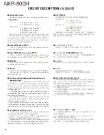
■
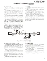
Shift register circuit
The MPU (IC34) transmits serial data to shift registers
IC923 from IC923 to IC960 and from IC960 to IC963 in the
display circuit (X56-312 B/3, C/3).
Additionally, it transmit serial data to the control unit (X53-
413) IC1 and IC22 and the transmitter unit (X56-312) IC703.
This serial data can control various functions of each unit.
■
Power supply circuit
This circuit consists of X53-413 IC6, IC10, IC11, IC15,
IC16 and 18, and X53-414 IC305, IC306, IC307 and IC329.
IC11 is a DC/DC converter that converts 13.2V to 5.0V.
IC10 is a DC/DC converter that converts 13.2V to 8.0V. IC16
is the 5.0V AVR and connected to IC10. IC6, IC15, IC305
and IC329 is the 3.3V AVR. IC18 is the 1.8V AVR. IC306 is
the 1.5V AVR. IC18 and IC306 is connected to IC329.
■
Flash ROM (RF control MPU)
IC17 is an 8M-bit Flash ROM and contains MPU fi rmware
for controlling the RF.
■
EEPROMs circuit
The EEPROM is a built in receiver unit (X55-310), trans-
mitter unit (X56-312) and Final unit (X45-386).
The RF control MPU controls these EEPROMs by the IIC
bus.
6-2. X53-414
■
Main MPU
The Main MPU (IC703) is a 32-bit RISC microprocessor
incorporating a 16K bytes cache memory.
The main MPU controls the Flash ROM, SDRAM, SRAM,
LAN IC, RS-232C driver, receiver and real-time clock (RTC)
IC besides RF control MPU and UART communication with
modem control MPU.
■
LAN interface
NXR-800H is equipped with a 100Base-TX or 10Base-T
LAN interface. This circuit consists of IC719, IC720 and
J700. IC719 is a control IC. IC720 is a EEPROM, and saves
the MAC address.
■
Real time clock (RTC) circuit
This circuit consists of IC710 and X701. IC710 is a Real
Time Clock. X701 is a crystal oscillator. IC710 is connected
to IC703 (Main_MPU) via the IIC bus. The oscillating fre-
quency of X701 is 32.768kHz. It is backed up by a recharge-
able lithium battery (BA300). The IC710 clock data is used
after resetting the backup.
■
RS-232C circuit
NXR-800H is equipped with a RS-232C interface. It is con-
nected to a PC with pin9 female RS-232C cross-wired cable.
It uses the FPU and writes the firmware. IC705 is a RS-
232C driver receiver IC, and interfaces at the TTL232C level.
■
Modem control MPU
Modem control MPU (IC325) is 16-bit single chip micro-
processor incorporating 256K bytes of ROM and 20K bytes
of RAM.
CIRCUIT DESCRIPTION /
电路说明
■移位寄存器电路
MPU(IC34) 将串行数据发送到显示电路 (X56-312 B/3,C/3)
中的移位寄存器 I C923,从 I C923 发到 I C960,然后从 I C960
发到 IC963。
此外,它还将串行数据发送到控制单元 ( X53-413) I C1 和
IC22 以及发射机单元 (X56-312)IC703。此串行数据可控制各
单元的各项功能。
■电源电路
该电路由 X53-413 I C6、I C10、I C11、I C15、I C16 和 18、
X53-414 IC305、IC306、IC307 和 IC329 组成。
I C11 是将 13.2V 转换为 5.0V 的 D C / D C 转换器。I C10 是将
13.2V 转换为 8.0V 的 DC/DC 转换器。IC16 是连接 IC10 的 5.0V
AVR。IC6、IC15、IC305 和 IC329 是 3.3V AVR。IC18 是 1.8V
AVR。IC306 是 1.5V AVR。IC18 和 IC306 连接 IC329。
■ Flash ROM(RF 控制 MPU)
IC17 是一个 8M-bit Flash ROM,含有用于控制 RF 的 MPU
固件。
■ EEPROM 电路
EEPROM 是内置接收机单元 (X55-310)、发射机单元 (X56-
312) 和末级单元 (X45-386)。
RF 控制 MPU 通过 IIC 总线控制这些 EEPROM。
6-2. X53-414
■主 MPU
主 MPU(IC703) 是一个 32 位 RISC 微处理器,采用 16K 字节
缓存。
除 R F 控制 M P U 和 U A R T 与调制解调器控制 M P U 的通信外,
主 MPU 还控制 Flash ROM、SDRAM、SRAM、LAN IC、RS-232C
驱动器、接收机和实时时钟 (RTC)IC。
■ LAN 接口
NXR-800H 配备 100Base-TX 或 10Base-T LAN 接口。该电路
由 IC719、IC720 和 J700 组成。IC719 是一个控制 IC。IC720
是一个 EEPROM,可保存 MAC 地址。
■实时时钟 (RTC) 电路
该 电 路 由 I C710 和 X701 组 成。I C710 是 一 个 实 时 时 钟。
X701 是一个晶体振荡器。I C710 通过 I I C 总线连接到 I C703
( 主 M P U )。X701 的振荡频率为 32.768k H z。它由一个可充电
锂电池 (BA300) 支持。备份重置后使用 IC710 时钟数据。
■ RS-232C 电路
N X R -800H 配备一个 R S -232C 接口。它通过 9 针母头 R S -
232C 交叉电缆连接到 P C。它使用 F P U 并写入固件。I C705 是
一个 RS-232C 驱动器接收器 IC,以 TTL232C 标准连接。
■调制解调器控制 MPU
调制解调器控制 M P U ( I C325) 是一个 16 位单片微处理器,
采用 256K 字节的 ROM 和 20K 字节的 RAM。
Summary of Contents for NXR-800H
Page 180: ...1 E CN300 RX_IF_VN 168 ...

