NXR-800H
25
D15
SW
D16
SW
CF2
CF3
D19
SW
D20
SW
DET
CF5
CF7
QUAD
10
8
6
4
15
17
IC20
(A/2)
Q40
IC29 (A/2)
D17,18
IC30
11 18
12
18
21
24
1
4
8
10
DIV
2nd local
49.5MHz
2nd local
49.5MHz
6
CF4
CF6
14
5DR
3DR
5NR
Analog Wide
Analog Narrow
NXDN Narrow
NXDN Very-Narrow
IC12
IC13
IC14
CN42
12
22
CN43
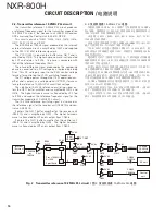
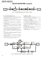
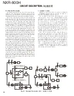
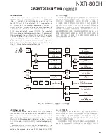
Fig. 19 Demodulator circuits /
图 19 解调器电路
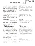
4-6. Receiver DDS circuit
The 19.2MHz Internal reference clock produced by trans-
mitter unit (X56-312 A/3) is distributed to CN45 of the re-
ceiver unit (X55-310). It passes through Q39, Q30, and IC8,
and is input to IC7 (DDS-IC) pin6 as the Master clock. Ap-
proximately 6MHz signal is generated as the 1st-PLL Refer-
ence clock.
IC7 has a resolution of 32 bits for realizing the frequency
step minters than the 1st-PLL comparison frequency. The
generated Reference clock is output via Q12, CF1, and Q5.
CF1 is a Ceramic Filter. It is the BPF for removing unneces-
sary spurious noise included in the generated Reference
clock.
LPF
LPF
LPF
LPF
BPF
+5V
Q5
+5V
+5V
Q12
+5V
Q30
+5V
Q39
CF1
IC7
DDS
14
6
+5V
IC8
1
5
DIV
CN45
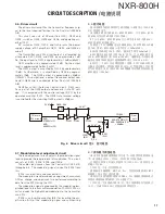
Fig. 20 Receiver DDS circuit /
图 20 接收机 DDS 电路
CIRCUIT DESCRIPTION /
电路说明
4-6. 接收机 DDS 电路
发射机单元 ( X56-312 A /3) 产生的 19.2M H z 内部基准时钟
被分配到接收机单元 (X55-310) 的 CN45。它通过 Q39、Q30 和
IC8,被输入到 IC7(DDS-IC) 针脚 6 作为主时钟。生成约 6MHz
信号,作为第 1 PLL 基准时钟。
I C7 具有 32 位的分辨率,用于实现小于第 1 P L L 比较频率
的频率步长。生成的基准时钟经 Q12、CF1 和 Q5 输出。CF1 是
一个陶瓷滤波器。它是消除所生成基准时钟中包含的不需要
的寄生噪声的 BPF。
Summary of Contents for NXR-800H
Page 180: ...1 E CN300 RX_IF_VN 168 ...


