NXR-800H
27
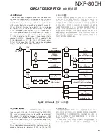
4-8. AVR circuit
The power supply voltage supplied from the power unit
(X45-386 C/5) is distributed from the receiver unit (X55-310)
CN44 to IC24 (8V), IC25 (8V), IC26 (9V), and IC27 (9V) via
the Q52 DC switch. The output of IC24 is supplied to the
1st-IF circuits, the 1st-Local amplifi ers and the IF system IC_
IC12 via IC15 (5V). Further, the output of IC25 is distributed
to IC16 (5V), IC17 (5V), IC18 (5V) and IC19 (5V). The output
of IC16 is supplied to IF system IC_IC13. The output of
IC17 is supplied to the 2nd-Local amplifi ers. The output of
IC18 is supplied to the 1st-PLL and the 2nd-PLL. The output
of IC19 is supplied to the DDS circuit. The output of IC26 is
supplied to LNA_Q1. The output of IC27 is supplied to the
VCO buffer amplifi ers_Q17, Q33, the 1st-VCO and the 2nd-
VCO via Active ripple fi lters_Q9, Q27, and to the Active loop
fi lter_Q2, Q4 via the Active ripple fi lters_Q6.
SW
+8V
+5V
CN44
+B
Q52
SW
Q32
IC24
+5V
IC16
+5V
IC17
+5V
IC18
+3V
IC10
+3.3V
IC22
+5V
Q9
Q27
Q6
IC19
+8V
IC25
Q18,23
1st local amplifiers
IC14
2nd IF amplifier
IC19
Pre-scaler
Q21,53
2nd local amplifiers
IC13
IF systemIC
Q19,28
WIDE pass
SW
Q25
Q20,29
Narrow pass
IC15
IC12
IF system IC
Q1
LNA (Collector)
Q1
LNA (Emitter)
+9V
IC26
+9V
IC27
+5V
IC701
–5V
IC702
–3V
IC703
IC5,11
1st/2nd PLL
ʹ
s
IC7
DDS
Q17,33
1st/2nd VCO buffer amplifiers
Q7,8
1st local VCO
ʹ
s
Q24
2nd local VCO
Q2,4
active loop filter
4-9. Other circuits
Other circuits include the EEPROM (IC31), the temper-
ature sensor IC (IC35), the DAC (IC23) and the ADC (IC30).
IC31 saves various adjustment values of the receiver unit.
IC35 is built-in for detecting changes in temperature. IC23
offsets the RSSI voltage (pin1) (detected by the IF system
IC (IC12)) and the 1st-VCO_A, VCO_B control voltage (pin2,
pin3).
IC30 monitors the 1st-VCO control voltage (pin16), the
LNA current detection value (pin15), the temperature de-
tected by the temperature sensor IC (IC35 pin14), the RSSI
CIRCUIT DESCRIPTION /
电路说明
4-8. AVR 电路
功率单元提供的电源电压从接收机单元 ( X55-310) C N44
经 Q52 D C 开 关 分 配 到 I C24(8V )、I C25(8V )、I C26(9V ) 和
IC27(9V)。IC24 的输出经 IC15(5V) 提供给第 1 IF 电路、第
1 本地放大器和 IF 系统 IC_IC12。此外,IC25 的输出被分配
到 IC16(5V)、IC17(5V)、IC18(5V) 和 IC19(5V)。IC16 的输
出被提供给 IF 系统 IC_IC13。IC17 的输出被提供给第 2 本地
放大器。IC18 的输出被提供给第 1 PLL 和第 2 PLL。IC19 的
输出被提供给 DDS 电路。IC26 的输出被提供给 LNA_Q1。IC27
的输出通过有源纹波滤波器 Q9、Q27 提供给 V C O 缓冲放大器
Q17、Q33、第 1 V C O 和第 2 V C O,通过有源纹波滤波器 Q6 提
供给有源环路滤波器 Q2、Q4。
Fig. 22 AVR circuit /
图 22 AVR 电路
4-9. 其它电路
其 它 电 路 包 括 E E P R O M ( I C31)、 温 度 传 感 器 I C ( I C35)、
DAC(IC23) 和 ADC(IC30)。IC31 保存接收机单元的各项调整值。
IC35 为内置式,用于检测温度变化。IC23 偏置 RSSI 电压 ( 针
脚 1)( 由 IF 系统 IC (IC12) 检测 ) 和第 1 VCO_A、VCO_B 控
制电压 ( 针脚 2、针脚 3)。
IC30 监测第 1 VCO 控制电压 ( 针脚 16)、
LNA 电流检测值 ( 针
脚 15)、温度传感器 IC (IC35 针脚 14) 检测的温度、IF 系统
Summary of Contents for NXR-800H
Page 180: ...1 E CN300 RX_IF_VN 168 ...


