NXR-901
73
■
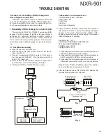
Traceability Procedure of IC323 (RX_DSP)
Confi rmation of Power Source Voltage
Test
Point Normal
Output
Voltage
IC307 (pin 1) 1.5VDC
IC15 (pin 3) 3.3VDC
Correct
condition
Confi rmation of Clock frequency
Test
Point Proper
Frequency
R678 12.288MHz
(either end of R678 is OK)
Correct
condition
Confi rmation of Reset control
Test
Point Normal
Control
Voltage
R521 3.3VDC
(either end of R521 is OK.)
Correct
condition
Parts other than IC323 are malfunctioning.
■
Traceability Procedure of IC314 (Flash Memory of modem control MPU)
Confi rmation of Power Source Voltage
Test
Point Normal
Output
Voltage
IC15 (pin 3) 3.3VDC
Correct
condition
Confi rmation of Reset control
Test
Point Normal
Control
Voltage
IC303 (pin 1) 3.3VDC
Correct
condition
Parts other than IC314 are malfunctioning.
Confi rmation of IC307 (pin 1) output
Remove R505. If the output voltage is 1.5VDC,
IC323 is malfunctioning.
Confi rmation of IC15 (pin 3) output.
Remove R487. If the output voltage is 3.3VDC,
IC323 or IC327 is malfunctioning.
If 12.288MHz oscillation cannot be confi rmed:
X300 is malfunctioning or a component around
X300 is malfunctioning
The clock oscillation amplitude is weak:
The circuit around X300 is malfunctioning.
Remove R521 and then confi rm the voltage at the
pad side of IC325:
If not 3.3VDC, IC325 is malfunctioning.
Remove R521 and confi rm the voltage on the pad
side of IC325:
If not 3.3VDC, IC323 is malfunctioning.
Abnormal
condition
Abnormal
condition
Abnormal
condition
Abnormal
condition
Abnormal
condition
Confi rmation of IC15 (pin 3) output.
Remove R417. If 3.3VDC, IC314 is malfunctioning.
Confi rmation of IC303 (pin 1) output voltage
If equal to or less than 3.3VDC, IC303 is malfunc-
tioning.
Remove R470 and confi rm the voltage of IC303 (pin
1).
If 3.3VDC, IC314 is malfunctioning.
TROUBLE SHOOTING
Summary of Contents for NEXEDGE NXR-901
Page 154: ...1 E CN300 RX_IF_VN ...


