NXR-901
14
CIRCUIT DESCRIPTION
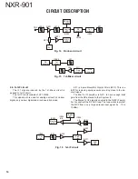
4-3. 1st-IF circuit
The IF1 signal produced by the 1st-Mixer circuit is
passed to 1st IF circuit.
The 1st IF circuit consists of XF1, Q204.
This signal path is used for analog narrow FM, narrow
digital, very narrow digital and mixed operation mode.
CN5
L203
L210
IC202
IC205
CN68
Q201
R210
IC201
Electric
ATT
IC811
#15
5V
RF
coupler
1st
mixer
RF AGC
control
XF1
Q10
Q11
IC205
RF
coupler
1st
mixer
Freq.
doubler
XF1
1st Lo
PLL block
XF1 is 4-pole Monolithic Crystal Filters (MCF). This is a
BPF for removing spurious noise occurring close to the de-
sired signal.
The fi nal 1st IF amplifi er is Q211 to have enough total
gain from the RX antenna to the IF system IC.
The fi ltered 1st IF signal is coupled to the Q202 IF ampli-
fi er to construct the RF AGC loop. The loop works to protect
the MCF from a very large antenna input signal (i.e. -10 to
10dBm).
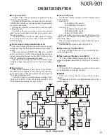
Fig. 14 Front-end circuit
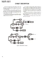
Fig. 15 1st-Mixer circuit
Fig. 16 1st-IF circuit
IC205
1st
mixer
IC202
Electric
ATT
IC805
#3
3dB
divider
XF1
Q202
Q211
3dB
divider
IC204
B/2
IC204
A/2
D203
Q204
Summary of Contents for NEXEDGE NXR-901
Page 154: ...1 E CN300 RX_IF_VN ...

