background image

8


|


CMOS-310/CMOS-210

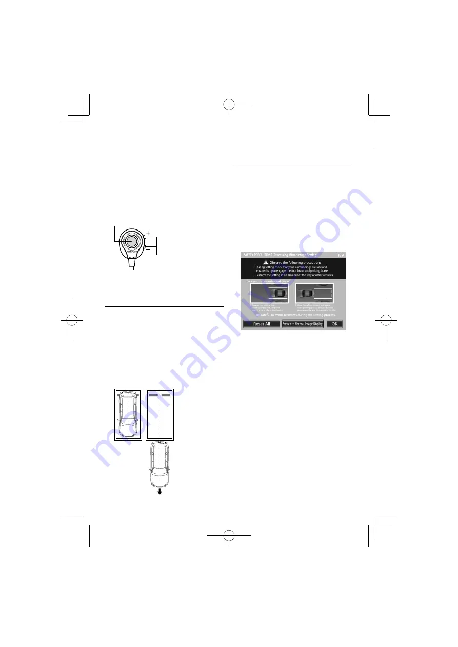
Switch Unit Operation

The switch unit can be used to switch the image display 
mode, view/hide the guideline display and adjust the 
camera.

View button

• Switches the image display mode.
• Select an item in the setting mode.
• Press and hold to display or hide the guidelines.

+/− 

button

Moves across the setting mode 
items or sets an adjustment value.

Preparation Before Camera Setting

1

  Stop the vehicle.

In a parking space with white lines and tire stoppers, park the 
vehicle in the center of the white line frame.

2

  Advance the vehicle.

•  Move the vehicle forward until the entire parking space can 

be viewed in the camera image.

•  Be sure to apply the parking brake and push the brake 

pedal so that the vehicle is completely stationary. Perform 
the setting in a place that will not cause nuisance to other 
people.

Camera Setting Procedure

1

  Complete all of the required connections in 

advance.

2

  Display the camera video.

Some video monitors may switch automatically to the 
external video input function. For details, read the instruction 
manual for your video monitor.

3

  Press and hold the view and + buttons of the 

switch unit simultaneously to enter the camera 
adjustment mode.

4

  First select the positioning of the camera.

Use the + or – button to select an item and press the view 
button to enter the selection.

• When using the camera as the rearview camera, select 

[OK].

•  When using the camera as the front camera, select 

[Switch to Normal Image Display] and then select [OK].

•  Selecting [Reset All] resets all of the camera settings 

to the defaults.

5

  Select a camera adjustment item and adjust it.

The following items are available for camera adjustment.

1.  Overhead view image adjustments

(Centering, Right-and-Left angle, Up-and-Down Angle)

2.  Wide view guideline adjustments

(Size, Horizontal direction, Vertical direction, Red Line 
Position Setting)

To select an item:

Press the + or – button to select an item and press the view 
button to enter the selection. When an adjustment item is 
selected, the frame of its icon turns from blue to red.

To adjust the item:

After selecting the item, press the + or – button to adjust it 
and press the view button to enter the adjusted value.

6

  End the setting.

Camera Setting (CMOS-310 only)


Summary of Contents for CMOS-210

Page 1: ...VISÃO UNIVERSAL CÂMARA TRASEIRA UNIVERSAL MANUAL DE INSTRUÇÕES 通用多图像摄像头 通用后视摄像头 使用说明书 B64 4963 08 00 W 2011 JVC KENWOOD Corporation Take the time to read through this instruction manual Familiarity with installation and operation procedures will help you obtain the best performance from your new Universal Camera For your records Record the serial number found on the back of the unit in the spaces ...

Page 2: ...onnect those wires to the power source running through the fuse box Do not cut out the fuse from the ignition wire Red The power supply must be connected to the wires via the fuse WARNING To prevent injury or fire take the following precautions To prevent a short circuit never put or leave any metallic objects such as coins or metal tools inside the unit Installation and wiring of this product req...

Page 3: ...ot attach the camera bracket to areas on the car body treated with fluorocarbon resin or glass May result in the rear view camera falling off Do not apply water to the unit Do not expose the unit to rain Do not subject the camera to unnecessary force Thoroughly clean where tape is used for sticking on the unit Refer to the Instruction s manual for details on connecting the other units then make co...

Page 4: ...pe according to the surface on which it will be attached Bend Bend Camera bracket Adjust the camera bracket shape so that it fits the camera installation position 5 Mount the camera on the camera bracket Mount so that the KENWOOD logo appears at the top 6 Fix the camera temporarily with tape etc Using a piece of tape etc fix the camera temporarily and adjust the angles so that the rear end of the ve...

Page 5: ...ra cord 11After adjusting the camera angle tighten the retaining screws firmly Inspect the retaining screws at times If they are loose tighten them firmly 12Perform the operations in Camera Setting page 8 CMOS 310 only If an adjustment is not possible in the currently available range change the camera position before retrying 13Fix the camera firmly in position Peel off the paper liner from the double...

Page 6: ...wer cord Before proceeding to connections make sure that the engine key is not inserted and disconnect the terminal of the battery to prevent the short circuiting incident Connect to the ON OFF switchable power supply Do not connect to a permanently ON power supply Fuse 2A Camera Connect the camera to the camera connection cord Connect to the rearview camera video input or to the external video in...

Page 7: ... cord System Connection CMOS 310 only Power cord To power supply When connecting the camera to a Kenwood navigation system etc Control unit equipped with the camera control function use the provided control unit connection cord This allows the control unit to switch the display view and adjust the camera as well on touch the control unit screen When using two CMOS 310 units for the front and rear ...

Page 8: ... function For details read the instruction manual for your video monitor 3 Press and hold the view and buttons of the switch unit simultaneously to enter the camera adjustment mode 4 First select the positioning of the camera Use the or button to select an item and press the view button to enter the selection When using the camera as the rearview camera select OK When using the camera as the front...

Page 9: ...adjustment item resets the camera setting of that item to the default Select to invert the icon upside down 3 After completing the adjustment press the view button Advances to OVERHEAD VIEW IMAGE ADJUSTMENT Right and Left ANGLE Overhead View Image Adjustment Right and Left Angle This item adjusts the horizontal angle in the rotary direction of the camera installation position 1 Select OVERHEAD VIE...

Page 10: ...e is 2 2 meters 7 22 feet Adjusting the wide view or overhead guidelines alters the interval between the corresponding guidelines As the interval between each set of guidelines varies depending on the camera installation height check the actual settings after all of the following adjustments are completed Once the interval between guidelines has been adjusted according to your parking space the di...

Page 11: ...ress the view button Advances to WIDE VIEW GUIDELINE ADJUSTMENT Horizontal direction Wide View Guideline Adjustment Horizontal Direction This item adjusts the left right positioning of the guidelines displayed in the wide view 1 Select WIDE VIEW GUIDELINE ADJUSTMENT Horizontal direction 2 Press the or button of the switch unit to adjust the left right positioning 3 After completing the adjustment ...

Page 12: ... Red Line Position Setting This item adjusts the position of the red line displayed in the wide view The red line can be used independently to set the reference line for the vehicle parking position 1 Select WIDE VIEW GUIDELINE ADJUSTMENT Red Line Position Setting 2 Press the or button of the switch unit to adjust the position of the red line By default the red line is superimposed with the yellow...

Page 13: ...rol function it is required to assign different camera IDs to the 2 cameras The camera IDs of both cameras have been set to ID1 at the factory 1 Press and hold the button of the switch unit for more than 2 seconds and then press and hold the button for more than 2 seconds 2 Press the or button of the switch unit to select the camera ID and press the view button 3 After setting press the or button ...

Page 14: ...raight up above the vehicle PinP View The overhead view is displayed on the upper half of the screen while the wide view is displayed on the lower half The overhead view in the upper half of the screen shows the area on the nearer side of the orange line shown in the wide view in the lower half Corner View The views seen from the two corners of vehicle are displayed on the left and right halves of...

Page 15: ... only Dimensions WxHxD 27 5 x 32 8 x 12 mm Weight Approx 10 g without cable General Operating voltage 14 4V 9 0 V 16 0 V Max current consumption CMOS 310 80 mA Max current consumption CMOS 210 60 mA Mirror image means that the video image inverts the left and right just like the image seen on the rearview mirror or a side mirror Specifications subject to change without notice This Product is not i...

Reviews: