CMOS-310/CMOS-210
|
13
ENGL
ISH
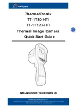
Finishing the Camera Setting
1
Press the + or – button of the switch unit to
select [Finish] and press the view button.
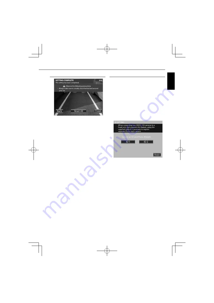
Camera ID Setting
When connecting two CMOS-310 units to a Kenwood
navigation system etc.
equipped with the camera control
function, it is required to assign different camera IDs to the
2 cameras. The camera IDs of both cameras have been set
to ID1 at the factory.
1
Press and hold the + button of the switch unit
for more than 2 seconds, and then press and
hold the – button for more than 2 seconds.
2
Press the + or – button of the switch unit
to select the camera ID, and press the view
button.
3
After setting, press the + or – button of the
switch unit to select [Finish] and press the view
button.