15
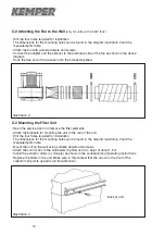
C-4 Attaching the Fan to the Filter Unit
(only for units with 0.75 kW fans)
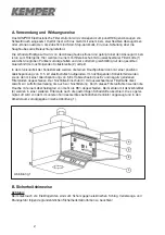
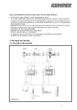
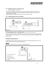
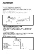
· Place the snap-fastener in an open position around the opening of the filter unit (see ill. 5).
· Place the fan with the intake side onto the opening and fasten it.
Make sure that the snap-
fastener latches completely.
· Mount the silencer to the air outlet side of the fan in the same manner.
C-5 Connecting the Fan to the silencer
C-6 Connecting the Fan to the Filter Unit
(only for units with 2,2 kW fans)
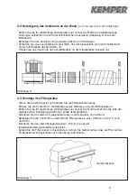
The intake nozzle of the fan is connected to the socket of the filter unit using the enclosed length
of hose and the two hose clips (see ill. 3). To do this, the hose may need to be shortened to the
required length.
D. Electrical Connection
Connect the control box, filter Unit, and the fan as shown in the following illustration and in the
wiring diagrams at the end of this Operating Manual.
Caution:
The following work should only be done by a qualified electrican!
Illustrator 5
➀
to the unit / filter monitor
➁
to the unit / fan
➂
power supply cable
➃
to the unit / high-voltage
generator
Summary of Contents for 150 0002
Page 2: ......
Page 53: ...51 I 5 Filterüberwachung Filter Monitor Contrôle de saturation ...
Page 54: ......
Page 55: ......
Page 56: ......


