Example
A flow switch is located 1000 metres from the T20 timer. Two separate wires each
0.2mm^2 are run to the remote flow switch (total wire length is 2000 metres). The
resistance as measured across the 2 wires back at the T20 (with the flow switch‘s
contacts closed is 190 Ohms. This is well under the 5,000 Ohm limit. The remote
input to the T20 will operate properly provide the wires are separated by suffi-
cient distance that the capacitance between them is less than 25nF. Capacitance
should be measured between the wires when the remote flow switch’s contacts
are open, and it must be less than 25nF.
Remote Flow Switch
The remote flow switch should be suitable for low voltage low current operation.
In particular its contacts should only require a low wetting current. The current in
the remote loop only runs to a few milliamperes and requires a flow switch that
will conduct when closed under low current conditions. Reed switches are the
preferred method of controlling the remote input to the T20 timer. Suitable Kelco
flow switch models are listed in the following table.
18
Note:
Resistance may vary depending on the wire standard and the actual con-
struction of the wire. The cable resistance refers to the total resistance out to the
remote flow switch and back again, as measured at the T20 timer across the 2
remote flow switch connection wires with the flow switch contacts closed.
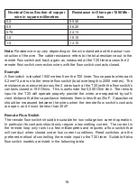
Nominal Cross Section of copper
wire in square millimetres
Resistance in Ohms per 1000 Me-
tres
0.2
95.30
0.5
36.20
0.75
24.13
1.0
18.10
1.5
12.10
Summary of Contents for T20
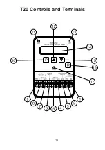
Page 17: ...T20 Controls and Terminals 15...
Page 34: ......


