KELCO T20 Installation & Programming Instructions Download Page 28

If you set this option to on, each time the pump stops, due to flow stopping the  

T20 will prevent the pump from restarting for the set period of time.  The delay 

time can be set from zero to 99 hours 59 minutes in increments of 1 minute.  De-

layed restarting is a form of anti-cycling and cyclic running, wherein the pump is 

limited in its ability to cycle on and off by preventing it from restarting for a set time 

period.  Its uses include preventing rapid cycling if the system’s air cell becomes 

water logged or if a fault develops in the system.  

Delayed Restarting

If you choose to use the delayed restarting function and press (P) you will be 

asked to enter the delay hours and minutes.  You will then be asked if you 

want automatic starting at the end of the delay period.  If you choose yes to 

this question the T20 will automatically start your pump at the end of the de-

lay period.  If you choose no the T20 will only start the pump after the de-

lay  if  flow  pushes  the  paddle  of  the  remote  flow  switch  into  the  on  position.

You may choose to set the delayed restart to perhaps 12 hours.  At the end of 

the 12 hour period the pump will automatically start and if the tank level is low, 

the pump will run continuously until the tank fills and the float valve in the tank 

closes.  If however, there has been no draw-off from the tank during the 12 hour 

period, the automatic restart at the end of the delay will start the pump and run it 

for whatever period you have set on the start timer (perhaps a few seconds).  The 

flow switch connected to the T20 will sense no flow because the float valve will 

still be closed.  The T20 will then shut down the pump and again wait for 12 hours 

before attempting to start the pump.  Using this technique prevents the pump from 

hunting on and off when the tank is full because of slight leakage from the float 

valve or pipework.  It allows you to set the pump to only operate after a chosen 

delay, and if there has been no usage of water, to test the system for demand by 

momentarily starting, and only run the pump if there is a genuine call for water.    

26

Summary of Contents for T20

Page 1: ...KELCO T20 TIMER INSTALLATION PROGRAMMING INSTRUCTIONS KELCO Engineering Pty Ltd Sydney Australia www kelco com au...

Page 2: ...ircuit Diagrams 10 The 12VDC T20 Timer 14 T20 Controls and Terminals 15 Remote Flow Switch Input 17 Suitable Flow Switches 19 Purging the T20 20 Programming the T20 Timer 21 Basic Operation 22 T20 Tab...

Page 3: ...tenance instructions in the lit erature accompanying the T20 timer WARNING This symbol is intended to alert the user to the presence of un insulated danger ous voltage within the timer s enclo sure th...

Page 4: ...way Do not drill holes in this timer s casing Refer all installation and servicing to qualified service personnel Servicing is required when the timer has been damaged in any way such as submerged in...

Page 5: ...water onto the T20 when the lid is not in place Always replace the lid and fully tighten its 6 securing screws imme diately after any changes to the timer s settings are made WARNING 3 INSTALLING THE...

Page 6: ...p The drilling pattern is shown below 60mm 74mm Attach the electrical housing to the wall bracket by engaging the two toes on the bracket into the two notches in the retainer plate on the underside of...

Page 7: ...ed from the mains It can also be operated from an 18 to 24V AC or DC supply by utilising the low voltage active terminal LV and common neutral terminal N see the included wiring diagrams When operated...

Page 8: ...to the T20 be isolated by an RCD that has a maximum trip current of 30mA WARNING Cables The T20 timer has 3 X M20 cable glands As supplied the cable glands are blanked off To use the glands first punc...

Page 9: ...he terminal block Relay 1 is the primary relay and is used to control the pump motor It has an electrical rating of 30 Amps resistive at 240VAC Relay 2 is a 16 Amp resis tive 240VAC rated relay and is...

Page 10: ...e used when the T20 is connected to external timers contactors relays or to any other external device where voltage free con tacts are required It is strictly intended for the direct control of highly...

Page 11: ...sistive Load 16A at 30VDC Resistive Load RELAY 2 CONTACT RATING 16A at 250VAC Resistive Load 16A at 30VDC Resistive Load Do not connect any supply greater than 25VAC or DC to the LV terminal on the T2...

Page 12: ...timer can be wired Please note all electrical work associated with the T20 timer must be car ried out by suitably qualified electricians and must conform to AU NZ wiring rules CONNECTIONS FOR PLUG PLA...

Page 13: ...ONTACTS AND HOW TO USE THE HD TERMINAL LOW VOLTAGE DC CONNECTIONS 18 TO 25 VDC 150mA MINIMUM SUPPLY POLARITY IS NOT IMPORTANT BUT IF THE EXTERNAL INPUT IS USED IT MUST BE SOURCED FROM THE SUPPLY POSIT...

Page 14: ...HASE PUMP MOTOR WITH REMOTE FLOW SWITCH INPUT AND AN EXTERNAL ALARM ACTIVE NEUTRAL MAINS VOLTAGE SUPPLY 220VAC to 240VAC ALARM LIGHT OR SIREN 220 240VAC DEVICE 16A MAXIMUM LOAD RESISTIVE CONTROLLING A...

Page 15: ...Y CONTROLLING A SINGLE PHASE PUMP MOTOR AS SHOWN HERE NEUTRAL ACTIVE MAINS VOLTAGE SUPPLY 220VAC to 240VAC ACTIVE NEUTRAL 18 to 25VAC SUPPLY PUMP MOTOR SINGLE PHASE 220 240VAC MOTOR MAXIMUM MOTOR LOAD...

Page 16: ...is correct When connecting a remote flow switch to the 12VDC T20 timer the supply to the flow switch must be taken from the positive terminal on the T20 timer The flow switch and its connecting circui...

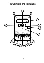
Page 17: ...T20 Controls and Terminals 15...

Page 18: ...or contactor 9 Heavy Duty Drive Ter minal Link this terminal to the relay 1 Normally Open terminal when directly controlling pump motors 10 Program Button Press this button to program the T20 timer 1...

Page 19: ...t the LV terminal is non iso lated and in terms of insulation must be regarded as operating at full mains potential whenever the T20 timer is powered from the mains The remote flow switch can be insta...

Page 20: ...low voltage low current operation In particular its contacts should only require a low wetting current The current in the remote loop only runs to a few milliamperes and requires a flow switch that wi...

Page 21: ...and BSP or NPT threads F20 S R P20 B P20 C TW20 S R F20 SS R P25 B P25 C TW20 SS R F21 S R UB20 B UB20 C TW21 S R F21 SS R UB25 B UB25 C TW21 SS R F25 B C20 B F25 C C25 B Full technical details of the...

Page 22: ...inal default state You can then enter new settings or just press reset R again and run the pump Purging the T20 Timer Introduction to Programming The T20 flow switch timer includes a set of functions...

Page 23: ...e recorded in the timer s memory Your setting will not be lost if the timer is switched off for extended periods When the unit is switched back on the timer will boot up and operate using the setting...

Page 24: ...This means they cancel out their runs and revert to normal pump running as soon as flow is detected rather than running for the full time that you have entered In addition the run on timer automatical...

Page 25: ...tch Controller Adjustable from 1 minute to 99 hours 59 minutes in 1 minute increments Delayed Restarting Adjustable from 1 minute to 99 hours 59 minutes in 1 minute increments Cyclic Running Stopping...

Page 26: ...le period It can be set from zero to 240 seconds 4 minutes in 1 second increments If you choose to use this timer the actual starting of your pump will be delayed by whatever delay you set this timer...

Page 27: ...ill work while the batch controller is in operation Functions that will not work with the batch con troller are automatically stepped over by the menu program Functions that will not work include cycl...

Page 28: ...the de lay if flow pushes the paddle of the remote flow switch into the on position You may choose to set the delayed restart to perhaps 12 hours At the end of the 12 hour period the pump will automat...

Page 29: ...he pump will run for the set period and then shut down It will not then restart until you again press the reset button or reset the power to the unit In cyclic running mode the T20 monitors the elapse...

Page 30: ...in any one hour period the pump will be automatically shut down and the T20 will display a message indicating the starts per hour rate was exceeded As a simple example of the way the anti cycling syst...

Page 31: ...ull capacity until the source of water was depleted It does this by using a timer that times out for a settable period each time the pump runs The timer resets back to its original setting each time t...

Page 32: ...ght switches on automatically whenever you are programming the timer and when the T20 is displaying certain fault conditions In normal operation the backlight remains off The LCD screen backlight can...

Page 33: ...Ltd A B N 20 002 834 844 Head Office and Factory 9 9 Powells Road Brookvale 2100 Australia Postal Address PO Box 7485 Warringah Mall NSW 2100 Phone 61 2 99056425 Fax 61 2 99056420 Email sales kelco c...

Page 34: ......

Reviews: