Operation
2-32
in the circuit under test. At the high resistance levels of many
Model 6512 measurements, however, leakage resistance can
have a detrimental effect on the measurement. Such leakage
resistance can occur in the circuit under test (on PC boards,
for example), in the connecting cable, or even at the elec-
trometer input itself, especially if the input connector is not
kept clean.
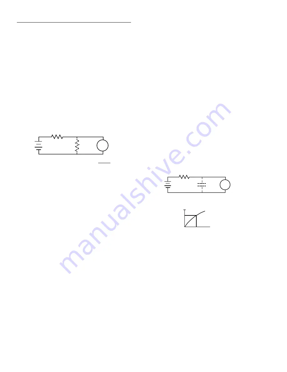
To see how leakage resistance can affect measurement accu-
racy, let us review the equivalent circuit in Figure 2-25. E
S
and R
S
are the source voltage and source resistance respec-
tively. The leakage resistance is represented by R
L
, while the
voltage, as seen by the electrometer, is V
M
.
Figure 2-25
Leakage resistance effects
R
S
and R
L
form a voltage divider that attenuates the input
signal in accordance with the formula:
Thus, if R
L
has a value of 100G
Ω
, and R
S
is 10G
Ω
, the ac-
tual voltage measured by the electrometer with a 10V source
would be:
V
M
= 9.09V
Thus, we see that the effects of leakage resistance can be sub-
stantial, resulting in an error of more than 9% in this case.
Certain steps can be taken to ensure that the effects of leak-
age resistance are minimal. The most obvious remedy to en-
sure that the leakage resistance itself is as high as possible.
Use only good quality triaxial cable for signal connections,
and make sure that the circuit under test and connectors are
kept free of contamination.
Even with these steps, however, there is a limit as to how high
the leakage resistance can be. In those cases, guarded input
connections should be used, as described in paragraph 2.7.4.
2.13.6 Input capacitance effects
Virtually any circuit has at least some small amount of dis-
tributed capacitance that can slow down the response time of
high-impedance measurements. Even if the circuit itself has
minimal capacitance, cable or instrument input capacitance
effects can be noticeable.
As an example, assume that the Model 6512 is being used to
measure the value of a high-impedance voltage source, as
shown in Figure 2-26. The source and source resistance are
represented by E
S
and R
S
, the input capacitance is C
IN
, and
the voltage measured by the electrometer is V
M
.
Figure 2-26
Input capacitance effects
When E
S
is first applied, the voltage across the capacitance
(and thus, at the electrometer input) does not instantaneously
rise to its final value. Instead, the capacitance charges expo-
nentially in accordance with the following formula:
Note that R
S
is given in megohms, C is in microfarads, while
t is in seconds.
RS
ES
RL
VM
VM =
ES RL
RS + RL
V
M
E
S
E
L
R
S
R
L
+
---------------------
=
V
M
10
100G
Ω
×
10G
Ω
100G
Ω
+
--------------------------------------------
=
RS
ES
CIN
VM
A. CIRCUIT
0.632 ES
RSCIN
B. EXPONENTIAL RESPONSE
V
M
E
S
1 e
t
–
RC
--------
–
=
Summary of Contents for 6512
Page 119: ...Maintenance 7 10 Figure 7 5 Exploded view...
Page 131: ......


