


Model 4200A-SCS Pulse Card (PGU and PMU) User's Manual
Section 2: Connections
4200A-PMU-900-01 Rev. A December 2020
2-5
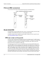
firmware upgrade of the 4225-RPM, the RPM LED is blue at the start, and changes to green for the
remainder of the process.
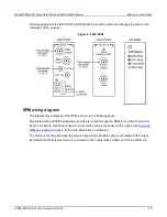
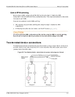
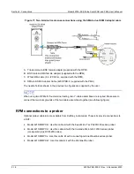
Figure 4: 4225-RPM
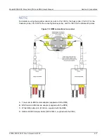
RPM wiring diagram
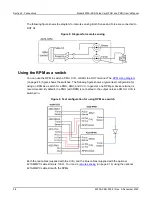
The internal wiring diagram of the RPM is shown in the following figure.
Signals from the 4200A-SCS instrument cards are routed through the RPM to the output Force and
Sense connectors. Switching is used to control which card is connected to the output. See
(on page 2-8) for more information on switching.
The LEDs on the top panel (see the previous figure) indicate which card is connected to the output.
By default, the RPM (pulse mode) is connected to the output unless a SMU or CVU is switched in.


