


Section 8: Testing flash memory
Model 4200A-SCS Pulse Card (PGU and PMU) User's Manual
8-20
4200A-PMU-900-01 Rev. A December 2020
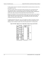
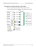
Make SMA-to-BNC connections to the pulse and SMU cards:
1. Connect an SMA-to-BNC adapter to one of the female connectors on an SMA tee.
2. Connect the tee to a triaxial-to-SMA adapter.
3. Connect a 20.3 cm (8 in.) SMA cable to the remaining SMA female connector.
4. Connect a 1.5 m (5 ft) black BNC cable to the BNC connection.
5. Repeat these steps twice.
6. Connect the SMA of one of the cable assemblies to CHANNEL 2 of the pulse card in the left-most
slot (the pulse card in the slot with the highest number).
7. Carefully insert the LEMO triaxial connector into the Force connector on the SMU in slot 4.
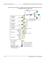
8. Route BNC cable from SMU4 to the DUT array WL2 terminal. If necessary, use a triaxial-to-BNC
adapter.
9. Connect the cable to the probe manipulator.
10. Connect the SMA of one of cable assemblies to CHANNEL 1 of the pulse card in the left-most
slot (the pulse card in the slot with the highest number).
11. Carefully insert the LEMO triaxial connector into the Force connector on the SMU in slot 3.
12. Route the BNC cable from SMU3 to the DUT array BL2 connection. If necessary, connect a
triaxial-to-BNC adapter.
13. Connect the cable to the probe manipulator.
14. Connect the SMA of one of the cable assemblies to CHANNEL 2 of the pulse card in the
right-most slot (the pulse card in the slot with the lowest number).
15. Carefully insert the LEMO triaxial connector into the Force connector on the SMU in slot 2.
16. Route the BNC cable from SMU2 to the DUT array WL2 connection. If necessary, connect a
triaxial-to-BNC adapter.
17. Connect the cable to the probe manipulator.
18. Connect the SMA of one of the cable assemblies to CHANNEL 1 of the pulse card in the
right-most slot (the pulse card in the slot with the lowest number).
19. Carefully insert the LEMO triaxial connector into the Force connector on the SMU in slot 1.
20. Route the BNC cable from SMU1 to the DUT array WL1 connection. If necessary, connect a
triaxial-to-BNC adapter.
21. Connect the cable to the probe manipulator.