


Section 8: Testing flash memory
Model 4200A-SCS Pulse Card (PGU and PMU) User's Manual
8-8
4200A-PMU-900-01 Rev. A December 2020
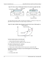
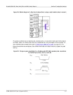
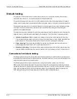
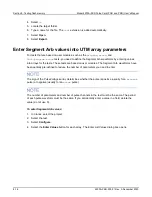
Figure 162: P Erase pulse waveforms for a floating gate DUT, with separate pulse
waveforms for the DUT gate, drain, source, and bulk
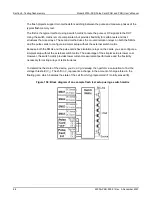
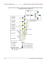
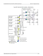
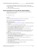
The block diagram for the flash setup is shown in the following figure. To reconfigure from the pulse
stress to dc measure phases, activate the switches on the SMU and pulse cards. During the pulse
program/erase phase, the relays in the pulse channels are closed and the relays in the SMUs are
open. For the dc measure phase, the opposite is true.
Figure 163: Basic schematic of flash testing without a switch matrix