background image


22 


DOC06820  Rev. A

SERVICE / REPAIR MANUAL 

RUNNING FLOOR II

®

 DX

5.3 

Component Identification / Function / Problems / Solutions
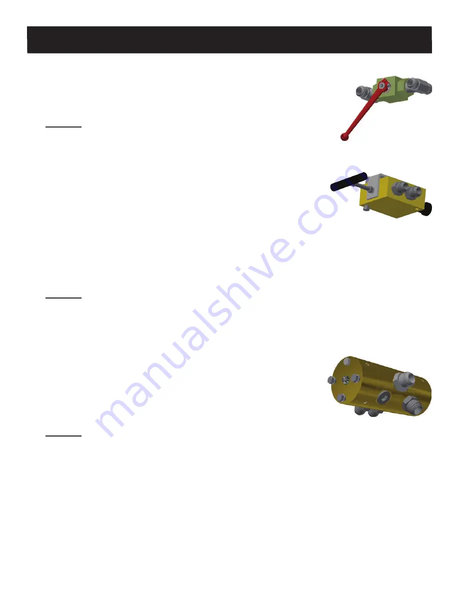
5.3.1 

Ball Valve (On /Off)

• 

A closed ball valve routes hydraulic oil flow to the drive system (floor On).

• 

An open ball valve redirects hydraulic oil flow back to tank (floor Off).

•  Emergency Stop

Problem:

 System will not operate or operates slowly.


9

Check to make sure the ball valve is fully closed (pulled out).


9

Check for sound of high-pressure oil bypass and/or excessive heat being generated.

Teflon ball seats could be damaged by heat (replace ball valve)

5.3.2  Control Valve (Load/Unload)

•  Controls which check valves are active, determining the direction of 

material movement (Load or Unload).

• 

Valve pulled out is in unload mode (material offloads).

• 

Valve pushed in is in the load mode (material loads).

Note: 

Control valves rarely fail under normal use, but may develop seal leaks over time. These leaks 

can be eliminated by installing new seals in the valve body. If damage or excessive wear is visible to the 
valve body or the valve spool, the valve must be replaced. If the valve has not been used for an extended 
period, it may become frozen in place due to contaminants on the valve spool. Do not operate the valve 
until it has been thoroughly cleaned of all contaminants and lubricated. Do not force the valve to operate. 
Doing so may cause internal damage to the valve body and spool.

Problem:

All cylinders move together to the front of the trailer and then all cylinders move together to the rear of 
the trailer. If this continues in both the unload and load cycles, the valve may be in the beginning stage of 
failure. Replace the valve. If the control valve is mounted on the outboard side of the trailer with hoses, 

check for the proper routing of the hoses. (Consult the Floor To Wet Kit Diagram for proper routing).

5.3.3  Switching Valve

•  Switches the hydraulic pressure from one end of the cylinders to the 

opposite end of the cylinders, which causes the cylinders to change from 
the restage sequence to moving the material then back again.

NOTE:


Many switching valves are unnecessarily replaced when they are 

only in need of adjustment. Switching valves almost always fail when they 

switch (all cylinders to the front or to the rear of the trailer), 

NOT


during the 

restage cycle or unload cycle.

Problem:

• 

(Unloading) All cylinders restage 1, 2, 3 to the front of the trailer and then the system stops.

• 

(Unloading) All cylinders move to the rear of the trailer and then the system stops.


9

Does the system show evidence of high-pressure bypass?

If so, the switching valve may not have switched. Check the threaded rods to see if they have fully 
actuated the switching valve. If not, readjust the switching valve. Be mindful that the front rod adjustment 
controls the timing of the restage cycle of the cylinders to the front of the trailer. The rear rod controls the 
timing of the cylinders for the unloading cycle. The same operating sequence happens, but in reverse 
during the loading cycle.

NOTE:

 If all the cylinders have stopped to the front or the rear of the trailer and the switching valve has 

been switched, try readjusting the switching valve first. If the system still does not work properly after 

adjustment, there is a high probability of switching valve failure and it needs to be replaced.

Summary of Contents for RUNNING FLOOR II DX

Page 1: ...SERVICE REPAIR MANUAL Original Instructions 2022 KEITH Manufacturing Co All Rights Reserved KEITH KEITH logo and WALKING FLOOR are registered trademarks of KEITH Manufacturing Co Equipment manufactur...

Page 2: ...4 Start Up 8 3 4 1 Before Initial Start Up 8 3 4 2 After initial 6 working hours first week of operation 8 3 5 Pre Trip Checklist 8 3 6 Standard Operating Procedures 9 3 6 1 Manual Controls 9 4 0 Main...

Page 3: ...6 5 4 1 Control Valve Replacement 26 5 4 2 Switching Valve Replacement 28 5 4 3 Switching Valve Adjustment 31 5 4 4 Check Valve Replacement 33 5 4 5 Cylinder Replacement 34 5 4 6 Cylinder Size Referen...

Page 4: ...improper use which could endanger life and limbs of personnel and cause severe damage to the equipment and other assets This equipment may only be used for its intended purpose It may only be operated...

Page 5: ...aterial Safety Data Sheet MSDS for the oil used in your system for further information about hydraulic oil safety 1 1 4 2 In an accident involving high pressure equipment hydraulic oil may be injected...

Page 6: ...v DOC06820 Rev A SERVICE REPAIR MANUAL RUNNING FLOOR II DX 1 2 Marking of Machinery 1 2 1 Safety Decals Safety Decal Placement Guide RUNNING FLOOR II w Manual Control Valve Left Side Controls...

Page 7: ...es Pump Flow Rate 5 60 gal min 19 227 liters min 5 60 gal min 19 227 liters min 5 50 gal min 19 189 liters min Recommended Pump Flow Rate 40 45 gal min 151 170 liters min 40 45 gal min 151 170 liters...

Page 8: ...tem Hydraulic Reservoir Sized to desired flow rate Should hold approximately 1 gallon 1 liter of oil for every gallon per minute liter per minute you plan to pump i e 40 gal min 151 liters min 40 gall...

Page 9: ...Pressure Relief Hose P T O IMPORTANT To ensure proper operation of your KEITH WALKING FLOOR the specifications and following diagram must be followed Failure to comply with these instructions may voi...

Page 10: ...l Valve Return Switching Valve Stage 3 Pressure still in rear of all cylinders Cylinder 2 completes its full stroke opening the check valve allowing the oil in cylinder 3 to escape to return causing i...

Page 11: ...ront of all cylinders Cylinder 2 completes its full stroke opening the check valve allowing the oil in cylinder 1 to escape to return causing it to move Load does not move Note Stage 3 requires more p...

Page 12: ...ressure Serial numbers are located underneath front stiffener plate Adapter Block Check Valves 2 Cross Drives 3 Right Side of Trailer 1 2 3 Cylinders 3 1 1 2 2 3 3 Control Valve Manual Left Side of Tr...

Page 13: ...of Trailer Return Pressure Serial numbers are located underneath front stiffener plate Adapter Block Check Valves 2 Cross Drives 3 Right Side of Trailer 1 2 3 Cylinders 3 1 1 2 2 3 3 Left Side of Trai...

Page 14: ...hing Valve Check Valve Adapter Block Control Valve Control Valve Manual or Electric Control Valve Electric Ball Valve Ball Valve Electric Manual Restrictor Valve Restrictor Valve Cylinder Cross Drive...

Page 15: ...uctions Loose cylinder barrel clamp bolts and flooring bolts are the most common cause of severe damage to the drive or flooring Any bolts that were loose should be checked weekly until found to be ti...

Page 16: ...handle in See figure above to the fully open OFF position The floor will not operate Ball Valve handle is located between the pressure and return lines NOTE The ball valve controls On Off and is used...

Page 17: ...e No single component should be warmer than 140 F 60 C while the system is running Torque cylinder barrel clamp bolts and floor bolts See 4 3 Maintenance section for special values and instructions An...

Page 18: ...183 N m Max 4 in Cylinder Barrel Clamp Bolts Requires blue Loctite 243 3 4 in GR8 HCS M20 CL10 9 HCS 4 per cylinder 180 ft lbs Max 244 N m Max Floor Bolts Flat Head 5 16 in GR8 FHCS 82 M8 CL10 9 FHCS...

Page 19: ...Valve Adaptor Block Bolts x24 Cylinder Barrel Clamp Bolts x12 Control Valve Bolt x1 Switching Valve Bolts x3 Cylinder Rod End Bolts x24 Floor Bolts Tube Clamp Bolts varies Cross Drive Assembly shown...

Page 20: ...led View 10021401 T Blocks Sub Deck Floor Slats Seal Standard Bearing Hold Down Bearing 4608302 T Block Seal Cross Sectional View Bearing 10005601 Sub Deck Splash Guard Hold Down Bearing Seal These im...

Page 21: ...arings attached to sub deck Floor Slats 09757801 J Bearings attached to sub deck Sub Deck Cross Sectional View J Bearings attached to sub deck These images are for illustrative purposes with colors mo...

Page 22: ...llowing items before calling your supplying dealer or KEITH Manufacturing Co for assistance 9 Confirm the relief valve is set for a relief pressure of 3000 PSI 9 Confirm the oil flow rate is within th...

Page 23: ...t can short across component assemblies ruining seals and gaskets KEITH sells flow meters pressure testers for troubleshooting and several tools to aid in rebuilding components and drives Use the foll...

Page 24: ...cylinders move in one direction and then stop 2 1 3 4 Cylinders switch direction before completing full travel to front or rear of trailer short cycling 2 1 5 System operates properly with light loads...

Page 25: ...emove some of the load Cause 6 Floor slats are jammed Solution Remove any material under the front slope shield Repair replace damaged slats Cause 7A Material is jammed or stuck Solution Use the contr...

Page 26: ...begin to move toward the rear 3 cross drive and cylinder move two to three inches back and forth Cause 1 The switching valve loop on the cross drive is bent and binding against the threaded rod Solut...

Page 27: ...Check Valve Replacement Problem 7 Cylinder s moves slowly while the other cylinder s move at normal speed Specific Problem In the Unload mode in empty tailer As all three cylinders travel toward the...

Page 28: ...r Installation Location Chart Cause 2 Insufficient pressure Solution Check the pressure and adjust the pressure relief valve if necessary see Specifications section Cause 3 Trailer is overloaded with...

Page 29: ...the unload and load cycles the valve may be in the beginning stage of failure Replace the valve If the control valve is mounted on the outboard side of the trailer with hoses check for the proper rou...

Page 30: ...e and one on 2 cylinder center Problem Unloading Material Cylinders are restaging to front of trailer Cylinders 1 2 restage together move at the same time to the front of the trailer There is a failur...

Page 31: ...e an issue with the pressure relief setting low oil flow or a pump issue Check the cylinders as described above and the pumping system for proper operational parameters NOTE It requires more pressure...

Page 32: ...and retighten the barrel clamps See Bolt Torque Requirements section If the system has been operated or continues be operated with over torqued clamps damage to the piston rings will occur resulting i...

Page 33: ...1 1 4 32 mm Open Ended Wrench 2 9 16 17 mm Open Ended Wrenches 1 9 16 17 mm Socket with Torque Wrench Control Valve Removal 1 Stop the floor and lockout tagout for safety 2 Clean the area with a shop...

Page 34: ...he drive frame and remove the control valve 8 Plug the remaining tube ends to keep them clean and from leaking fluid Control Valve Installation 9 Install the new control valve and torque the 4 bolts S...

Page 35: ...ocket with Torque Wrench Switching Valve Removal 1 Cycle the floor until all three of the cross drives are approximately in the center of the drive 2 Stop the floor and lockout tagout for safety 3 Cle...

Page 36: ...the ends away from the switching valve 7 Plug the loose ends of the fittings to keep them clean and from leaking fluid 8 Loosen the ends of the tubes connected to the PUMP RES ports 9 Support the swit...

Page 37: ...and tighten See Service Information chart 13 Install the threaded rod with the limit cap on the opposite side of the switching valve from the mounting bracket Install the threaded rod with the large f...

Page 38: ...d of the stroke Immediately push the ball valve handle in toward the center of the trailer to stop the drive unit This will allow the hydraulic oil to bypass the system At this point the cylinders wil...

Page 39: ...alve Adjustment Diagram 1 3 8 10 mm Threaded Rod 2 5 3 8 10 mm Lock Washers 2 2 3 8 10 mm Nuts 6 6 Switching Valve Grommet 2 3 3 8 10 mm Flat Washers 5 7 Limit Cap 4 Switching Valve Control Valve Asse...

Page 40: ...tube nuts on the opposite ends of those tubes and rotate the tubes away from the check valve 7 Plug the tube ends to keep them clean and from leaking fluid 8 Loosen the 4 bolts and remove the check va...

Page 41: ...oist or Extra Person Cylinder Removal 1 Cycle the floor until all cylinders are approximately in the center of the drive 2 Stop the floor and lockout tagout for safety 3 Clean the area with a shop rag...

Page 42: ...t each end of the cylinder 11 Use the Cylinder Installation Location Guide to verify that the cylinder is positioned accurately and that the threaded pad is mated appropriately with the upper threaded...

Page 43: ...ing the circumference of the cylinder or measuring the outside diameter of the cylinder and referencing the following chart Cylinder Size Reference Chart Standard Cylinder Centers Cylinder Bore Size I...

Page 44: ...12 3 4 1 1 4 13 Nutbar Shoe 6 1 16 14 5 16 1 1 2 12 3 4 Pressure Seal 1 5 16 12 23 32 1 9 32 12 11 16 Pressure Seal Lite 1 9 16 14 5 16 1 1 2 12 3 4 V 9 1 11 16 12 13 16 1 11 16 12 3 4 1 3 8 13 V 18...

Page 45: ...tion Website www KeithWalkingFloor com Email TechDept KeithWalkingFloor com Toll Free 800 547 6161 Phone 1 541 475 3802 6 0 Contact Information KEITH Manufacturing Co World Headquarters USA 401 NW Adl...

Reviews: