MCB517AC Evaluation Board User’s Guide
15
CAN
GND
+5V
CAN_L
CAN_H
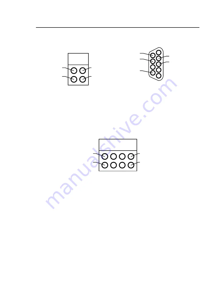
CAN Connector (DB9M)
GND
op5V
CAN_L
CAN_H
1
6
5
9
optional GND
CAN Ports
In addition to the CAN receive and transmit lines the 81C90 full CAN controller
has two 8 bit I/O port extensions. Each of these pins can be configured as input
or output depending on the contents of the port-direction register. Refer to the
figure below how these ports are wired.
CAN Port_x
Port_x.0
Port_x.1
Port_x.6
Port_x.7
Prototyping Area
A perforated area is provided on the MCB517AC for prototyping your own
hardware. All data- and address-bus signals as well as all ports are connected to
the first two rows of the prototyping area. The signals provided are driven
directly by the CPU. Exercise caution to avoid overloading these signal lines.
The following figures show how the ports and bus lines are connected to the
prototype area. Please note that some ports are connected in reverse order.
Summary of Contents for MCB517AC
Page 6: ...vi Contents...
Page 23: ...MCB517AC Evaluation Board User s Guide 17 Schematics...
Page 24: ...18 Chapter 3 Hardware...
Page 25: ...MCB517AC Evaluation Board User s Guide 19...
Page 26: ...20 Chapter 3 Hardware...
Page 27: ...MCB517AC Evaluation Board User s Guide 21 Printed Board Assembly...
Page 32: ...26 Chapter 3 Hardware...
Page 34: ......


