4
Chapter 2. Setup
Using the MCB517AC
To use the MCB517AC evaluation board, you must:
n
Connect the external serial port jack (COM 0) to an serial port on your PC
using the supplied serial cable.
n
Connect power using a standard power supply.
The serial cable lets your PC download program code and debug your target
applications. The power cable provides power to the MCB517AC evaluation
board. The MCB517AC does not get power from the PC via the serial cable.
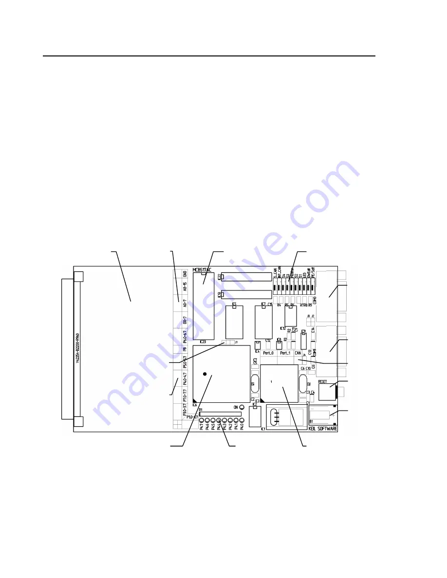
The following illustration shows MCB517AC board and the important interface
and hardware components.
Power
Supply
DIP
Switches
Serial
Interface 0
Serial
Interface 1
Reset Button
Monitor
EPROM
80C91 Full CAN
Controller
80C517 / 80C537
or 80C517A / 83C517A
Port 1 Status
LED’s
Prototyping
Area
Bus
Signals
Port
Signals
Configuration
Jumper
CAN
Interface
Summary of Contents for MCB517AC
Page 6: ...vi Contents...
Page 23: ...MCB517AC Evaluation Board User s Guide 17 Schematics...
Page 24: ...18 Chapter 3 Hardware...
Page 25: ...MCB517AC Evaluation Board User s Guide 19...
Page 26: ...20 Chapter 3 Hardware...
Page 27: ...MCB517AC Evaluation Board User s Guide 21 Printed Board Assembly...
Page 32: ...26 Chapter 3 Hardware...
Page 34: ......


