21
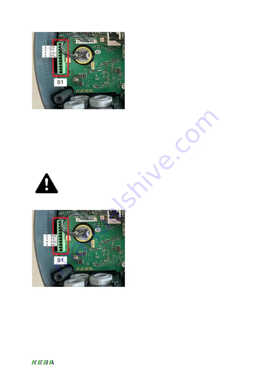
Illustration: Picture of the base station with terminal strip S1 - contacts for enabling switches (pin 2 to 5)
7.3. Emergency stop
The emergency stop is designed according to the closed loop principle. By pressing the emergency
stop - either on the base station or on the handheld terminal - the circuits in the base station are
interrupted - these outputs are closed in normal operation. These outputs must be read in as inputs in
a PLC or safety controller, there is no possibility to read them out in the handheld terminal.
If the emergency stop was triggered, the bar of the base station turns red. Releasing the emergency
stop switches back to the previously valid state.
The emergency stop has two circuits, please refer to the manual for details.
As these are safety devices, please read the manual.
The contacts for the emergency stop are available on terminal strip S1 pin 6 to pin 9.
Illustration: Picture of the base station with terminal strip S1 - contacts for emergency stop (Pin 6 to 9)


