


GB - 18
GB
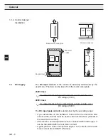
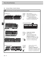
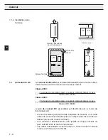
Connection of Power Circuit
T1
T2
T1
T2
Braking resistor
External temperature
monitoring
Thermojunction
(NC-contact)
Temperature sensor (PTC)
1650
Ω
...4k
Ω
tripping
resistance
750
Ω
...1650
Ω
reset resistance
Do not lay connecting cable (also
shielded) together with control cable!
Permissible in the motor cable only
with double shielding!
To carry out an evaluation activate the function by way of the software
(F5-B/G) of the control card (CP.28 / see control part).
T1
T2
F5-M/S:
Bridge, when no
monitoring occurs
Observe safety instructions of part 1!
Braking resistors can
develop a very high
surface temperature, therefore
install as safe-to-touch as
possible!
230 or 24 V
AC/DC
supply
at 24 V AC/DC
check tripping
*)
*) depending on the housing size
the te+, +PA or PA can
be used
U
V
W
PB
L3
N/L2
X1A
T1
T2
--
L1
++
PA
PB
OH1
OH2
U
K1
11
12
T1
K1
12
11
T2
Temperature sensor
(PTC)
Other
During clearing of the temperature monitoring the input voltage is
switched off. For additional protection in regenerative operation connect
the auxiliary contacts 11 and 12 of the line contactor K1.
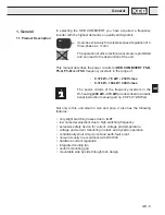
Summary of Contents for COMBIVERT F5 Series
Page 4: ...D 4 D...
Page 20: ...D 20 D...
Page 22: ...GB 4 GB...
Page 38: ...GB 20 GB...
Page 40: ...F 4 F...
Page 56: ...F 20 F...
Page 58: ...I I 4 I...
Page 74: ...I I 20 I...
Page 76: ...RU 4 RU...
Page 79: ...RU 7 RU 1 3 1 3 1 KEB COMBIVERT F5 40 C 4...
Page 92: ...RU 20 RU...
Page 94: ...E 4 E...
Page 110: ...E 20 E...
Page 111: ......
Page 112: ......
Page 113: ......
Page 114: ......


