45
INSTALLATION AND CONNECTION
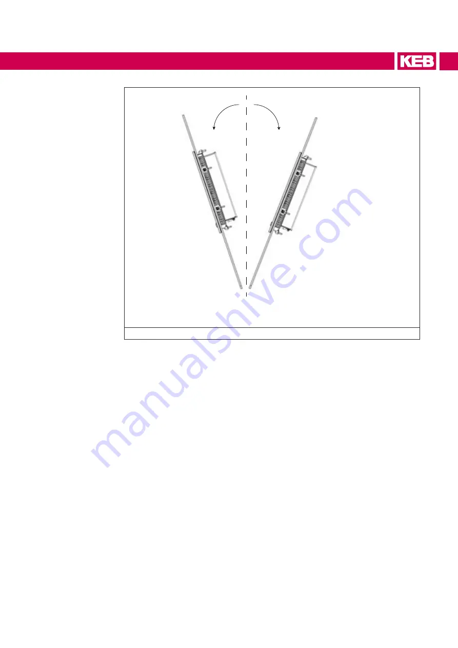
0°
20° max
20° max
Figure 37: Inclined Installation
3.6 Selection of the installation panel
In order to ensure a proper mounting of the system, the material of the installation panel
(with the installation panel cut-out) must be stable.
To obtain the degree of protection described below, the material of that mounting panel
must not deform, due to the use of clamps.
3.6.1 Degrees of protection
The front degree of protection of the system (IP) is guaranteed only if the following con-
ditions are satisfied:
• The material thickness of the installation panel (with the mounting cut-out): 2mm to
6 mm.
•
Maximum deviations: ≤ 0.5 mm. That condition must be met after installation, in
order to guaranteed proper operation of the mounting seal.
•
Allowed surface roughness in the area of the mounting seal: ≤ 120 microns (Rz 120).
Summary of Contents for C6 E22 BM-RVL
Page 1: ...EMBEDDED IPCS INSTRUCTIONS FOR USE E22 BOX PANEL Original Manual Document 20146638 EN 01 ...
Page 2: ......
Page 11: ...11 List of Figures Figure 89 External connectors 108 Figure 90 Buttons position detail 108 ...
Page 48: ...48 Installationand connection ...
Page 96: ...96 Drawings 7 1 4 C6 E22 PANEL SL S1 12 1 W Figure 75 12 1 Wide dimensions ...
Page 110: ...110 Certificatesandapprovals 8 Certificates and approvals 8 1 EU Declaration of conformity ...
Page 111: ...111 Certificatesandapprovals ...
Page 114: ......


