49
INSTALLATION AND CONNECTION
3.8 Mounting the device
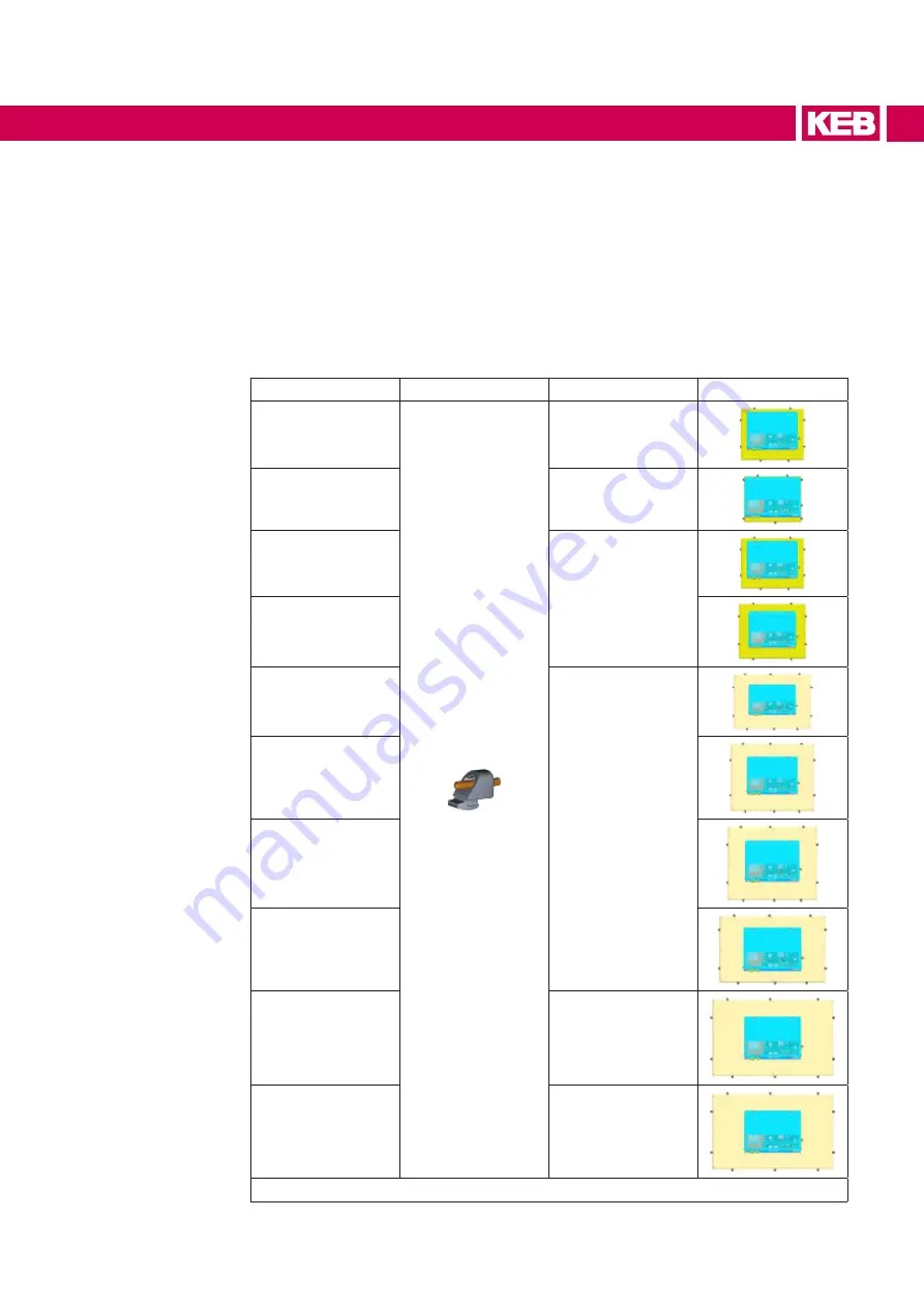
3.8.1 Position of the mounting clamps
• To obtain the declared degree of frontal protection for the system, it is necessary to
follow the positions of the clamps shown below.
• The table below shows the number and the position of the clamps for each C6 E22
PANEL size.
LCD size
Clamp
Quantity
Clamp position
10.1“
8
10.4”
8
12.1”
8
15.0”
15.6”
10
17.0”
18.5”
19.0”
21.5”
14
24.0”
14
Table 7:
Position of the mounting clamps
Summary of Contents for C6 E22 BM-RVL
Page 1: ...EMBEDDED IPCS INSTRUCTIONS FOR USE E22 BOX PANEL Original Manual Document 20146638 EN 01 ...
Page 2: ......
Page 11: ...11 List of Figures Figure 89 External connectors 108 Figure 90 Buttons position detail 108 ...
Page 48: ...48 Installationand connection ...
Page 96: ...96 Drawings 7 1 4 C6 E22 PANEL SL S1 12 1 W Figure 75 12 1 Wide dimensions ...
Page 110: ...110 Certificatesandapprovals 8 Certificates and approvals 8 1 EU Declaration of conformity ...
Page 111: ...111 Certificatesandapprovals ...
Page 114: ......


