background image

1-800-KEATING


|


ELECTRIC CUSTOM PASTA SYSTEM - SERIES 2009

9

NOTE:

 Use of sodium chloride

 (salt)

 during the cook-

ing process will have a detrimental effect on the cooker 
vessel and will void the warranty. 

WHEN THE WATER LEVEL FALLS BELOW THE BOTTOM 
WATER SENSOR THE HEATING ELEMENTS WILL TURN 
OFF. IF THEY CONTINUE TO HEAT, TURN THE MAIN 
POWER SWITCH OFF AND CHECK AUTO-FILL SYSTEM.

LIMITED CALIBRATION

(Less than 15° difference) 

A. Calibration

Calibration is not covered under warranty. 

NOTE:

 This procedure can only be used with the primary 

(left side) thermostat. When calibrating the secondary 
(right side) thermostat.

You will need: 

   One standard fl at blade screwdriver.

   One accurate thermometer suitable for boiling water.

NOTE:

 For best results, water should be clean.

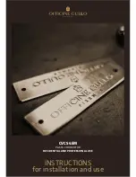
1. Set thermostat to 212°F (190°C).

2. Allow Pasta System to cycle three times. 

3. Place an accurate thermometer in the water.

NOTE:

 Locate thermometer in same position for every 

calibration. Position near primary thermostat (center) 
bulb is recommended.

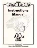
4. Pre-2000 model: If calibration of thermostat is 
    found to be less than 15°F (-9.44°C) off, simply 
    loosen three dial plate retaining screws, rotate 
    dial plate to match thermometer reading and 
    tighten screws.

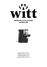
    2000 model: If calibration is found to be less 
    than 15°F (-9.44°C) off, remove thermostat knob. 
    Loosen four screws in thermostat dial plate. 
    Replace knob. Reset dial plate to match 
    thermometer reading. Remove knob to tighten 
    screws on dial plate and replace knob.

    If the thermostat is more than 15°F (-9.44°C) off 
    then a qualifi ed service company must be 
    contacted to have the Pasta System properly 
    calibrated.

B. The Water Auto-Fill and Low Water 
     Safety Shut-Off Systems

The water supply connection, located at the bottom rear 
of the Pasta System and marked water, is a standard 
3/8" female pipe connection. The water pressure 
should be between 20-60 psi. If the pressure exceeds 
60 psi, a pressure regulator must be used. The water 
temperature must not exceed 150°F (65.6°C). Hot or 
warm water is not needed due to the instant recovery of 
the Pasta System.

Connections suitable for hot water must be used. All 
connections must be tested for leaks before using the 
Pasta System.

NOTE:

 For Pasta Systems with casters, fl exible hose 

must be used to avoid leaking when the Pasta System 
is moved for cleaning.

Control of the water level is fully automatic with the 
auto-fi ll system. The water level is controlled by two cir-
cuit boards and two sensors. The sensors are located 
in the tube on the right side of the overfl ow deck. The 
upper sensor controls the water level and the lower sen-
sor controls the low water safety shut-off system. Once 
the water On/Off switch is turned on, the blue light will 
come on and start to fi ll until the water level reaches 
the upper sensor. The burners will not come on until 
the water level reaches the lower sensor, preventing the 
Pasta System from being damaged if there is little or no 
water in it. Both sensors must be cleaned with the sen-
sor brush (like the one provided) on an hourly basis or 
whenever starch foams up to maintain the proper water 
level. Sensors must be cleaned more often in areas 
with hard water, in installations with softened water (due 
to the salt in the water) or when oil or salt is placed in 
the water for cooking.

Figure 5

Thermometer in water

Thermometer

Figure 6

Thermostat Calibration

Thermostat knob 
removed to reveal 
calibration screws

Thermostat Calibration
2000 Model

Summary of Contents for 14 Counter

Page 1: ...rmed it is in your interest to obtain and keep all receipts Keating Custom Pasta System is not intended for household use As continuous product improvement occurs specifications may be changed without...

Page 2: ...ND THE FOOD SERVICE SANITATION MANUAL OF THE FOOD AND DRUG ADMINISTRATION FDA 9902091 9902091 i Improper installation adjustment alteration service or maintenance can cause property damage injury or d...

Page 3: ...UCTIONS Proper installation will assure top performance Alterations of any kind to your equipment will void the warranty Before uncrating check equipment carefully for damage IF EQUIPMENT ARRIVES DAMA...

Page 4: ...Pasta Systems come with all the same features as the standard models The Basket Lift mechanism lowers the baskets of food into the water when the timer button is pressed and raises the baskets when th...

Page 5: ...ND MAINTAINED IN ACCORDANCE WITH THE MANUFACTURER S IN STRUCTIONS THIS PRODUCT COULD EXPOSE YOU TO SUBSTANCES IN FUEL OR IN FUEL COMBUSTION WHICH CAN CAUSE DEATH OR SERIOUS ILLNESS AND WHICH ARE KNOWN...

Page 6: ...S 1 On Pasta System installations with casters the casters and jam nuts must be completely tightened Adequate means must also be provided to limit the movement of the appliance without depending on th...

Page 7: ...water is absorbed in food and lost in the form of steam Use the following steps to properly set this feature 1 Fill the unit to the FILL LINE with water 2 Rotate potentiometer clockwise as far as pos...

Page 8: ...on a regular basis to prevent water depos its from interfering with the sensor reaction Cleaning should be done with the brush up and down the sensor tube located on the right side of the splashdeck C...

Page 9: ...stant footwear 2 Turn thermostats to OFF 3 After water cools drain the water 4 Turn Pasta System on and fill vessel with water See page 5 Filling UNDER NO CIRCUMSTANCES SHOULD THE PASTA SYSTEM BE LEFT...

Page 10: ...close During the countdown the colon will flash at a one second rate When the countdown has reached 00 00 the relay output contacts will open the display will flash and the audible alarm will sound T...

Page 11: ...Water Auto Fill and Low Water Safety Shut Off Systems The water supply connection located at the bottom rear of the Pasta System and marked water is a standard 3 8 female pipe connection The water pre...

Page 12: ...IS DONE PRIOR TO SHIPMENT AT THE FACTORY IT SHOULD ONLY BE ADJUSTED BY A QUALIFIED SERVICE TECHNICIAN The potentiometer is located on the control board It is a black knob with a white triangle imprint...

Page 13: ...ve the wire from the top sensor If filling begins replace the sensor Part 010212 e If water does not fill place a jumper wire across terminals A C on the B Board If filling begins replace B Board Part...

Page 14: ...rmostat contacts do not close properly a Contact your electrician or the local power company and have the incoming power checked b Replace contactor c Tighten connections d Replace thermostat Basket L...

Page 15: ...ARNING AND OPERATING PLATES All warning and operating plates on the Keating Pasta Cooker should be in place at all times If plates are damaged or lost replace them immediately PARTS LIST CUSTOM PASTA...

Page 16: ...1 1 1 TERMINAL BLOCK 3P SMALL 002565 CIRCUIT BREAKER 40AMP 1P 012129 4 6 6 4 FUSE 300V 3AMP 004334 2 2 2 2 CONTACTOR 110V 3P 50AMP 011225 3 3 3 2 CONTRACTOR 110V 4P 40AMP 005597 1 TRANSFORMER STEPDOWN...

Page 17: ...1 800 KEATING ELECTRIC CUSTOM PASTA SYSTEM SERIES 2009 15 WIRING DIAGRAMS 14 ELECTRIC PASTA 2 THERMOSTAT WIRING DIAGRAM WITHOUT TIMERS...

Page 18: ...keatingofchicago com 16 14 ELECTRIC PASTA WITH DIGITAL TIMERS WIRING DIAGRAM...

Page 19: ...1 800 KEATING ELECTRIC CUSTOM PASTA SYSTEM SERIES 2009 17 14 ELECTRIC PASTA WITH 138 TIMERS WIRING DIAGRAM PRE 2000 SERIES BLACK DIAL TIMER NOT DIGITAL...

Page 20: ...keatingofchicago com 18 14 ELECTRIC PASTA WITH BASKET LIFT AND DIGITAL TIMERS WIRING DIAGRAM...

Page 21: ...1 800 KEATING ELECTRIC CUSTOM PASTA SYSTEM SERIES 2009 19 18 20 ELECTRIC PASTA WITH 138 TIMERS WIRING DIAGRAM PRE 2000 SERIES BLACK DIAL TIMER NOT DIGITAL...

Page 22: ...keatingofchicago com 20 18 ELECTRIC PASTA 2 THERMOSTAT WIRING DIAGRAM WITHOUT TIMERS...

Page 23: ...1 800 KEATING ELECTRIC CUSTOM PASTA SYSTEM SERIES 2009 21 24 ELECTRIC PASTA WITH DIGITAL TIMERS WIRING DIAGRAM...

Page 24: ......

Page 25: ......

Page 26: ...RANTY CARD ON OUR WEBSITE FOR YOUR CONVENIENCE COMPANY ADDRESS CITY STATE ZIP CODE DEALER NAME DATE OF PURCHASE INVOICE SERIAL MODEL I HAVE READ THE INSTALLATION AND OPERATING INSTRUCTIONS SIGNED DATE...

Reviews: