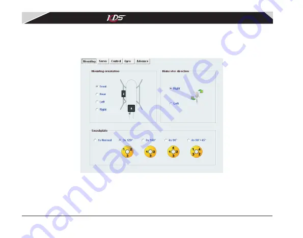
background image

15

3.3 Adjusting

 '

Mounting


parameters

'

The  page  'Mounting'  is  some  basic  parameters  relate  to  mechanism,  they  must  be  configured


correctly  so  that


Flymentor  3D  can  work.  The  interface  is  shown  as  diagram


3.3.1

there


are


three


categories

mounting


direction, rotor direction, swashplate type.

Diagram


3.3.1

 '

Mounting

page

1)

Mounting orientation

There is an arrow printed


on


Sensor


and


CCD


of


the


Flymentor 3D

You


can


point


the


arrow


to


any


direction


when


mounting

but


the


two


arrows


must


point


to


same


direction

 (

and


lens


of


CCD


must


face


to


ground

) . 

Normally

the


arrows

point to 

front  (helicopter  head).  After  mounting,  you  should  set  this  parameter  according  to  the 


are


KDS Flymentor 3D


User


Manual

07-17-平衡仪说明书(英文).pdf   18

2009-8-3   15:06:46

Summary of Contents for Flymentor 3D

Page 1: ...Flymentor 3D WWW KDSMODEL COM User Manual SHENZHEN KDS MODEL TECHNOLOGIES CO LTD...

Page 2: ...3 Attentions 1 4 LED status 1 5 Using flow 2 Connect to computer 2 1 Installing driver 2 2 Adjustment and Saving 3 Mounting stage 3 1 Setup transmitter 3 2 Mounting Flymentor 3D 3 3 Adjusting Mounting...

Page 3: ...justing Gyro parameters 4 1 1 Gyro settings 4 1 2 Gyro Expert Setting 4 2 Adjusting Advance parameters 4 2 1 Working mode 4 2 2 Basic parameters 4 2 3 Mode parameters 4 2 4 Expert settings 5 Usage of...

Page 4: ...re using Flyementor 3D if you are not sure about these it is recommended to find an old hand to help you Attention The software may be different from this manual because of upgrading of the software P...

Page 5: ...ler it is kernel of Flymentor 3D and takes charge of balance calculating and servos controlling The Receiver Connect Line is used to link receiver to obtain signal The Device Connector is used to link...

Page 6: ...king gyro and swashplate mixer Control sensitivity and mode of internal gyro through GEAR channel Support swashplate 3S 120 3S 140 4S 90 4S 90 45 Keep balance in inverted flight Configured by computer...

Page 7: ......

Page 8: ...ning mode on Under positioning mode balancing function and anti drifting function Green blink Positioning mode failed CCD can not obtain enough contrast can not switch to positioning mode the Flymento...

Page 9: ......

Page 10: ...DS USB adapter Plug into USB port Driver of USB adapter Configure software Diagram2 1 1 Connect Flymentor 3D with computer First please plug the USB adapter into Flymentor 3D then plug USB refer to di...

Page 11: ...automaticlly after it running if it could not find the adapter a balloon will be shown as diagram2 1 3 Please confirm the adapter was connected properly then click Retry If the apapter can not be fou...

Page 12: ...software will try to communicate with Flymentor 3D If the Flymentor 3D is not power on you will see No device on status bar Otherwise it will show Connected after few seconds shown as diagram 2 1 4 D...

Page 13: ...click Read button see diagram2 2 1 Read button Diagram 2 2 1 Read parameters After reading you will see configure page on the right side of the software like diagram2 2 2 You can use mouse to drag the...

Page 14: ...in Flymentor 3D and no necessary to write If they are not equal a exclamatory mark will show to notify you 3 Mounting stage 3 1 Setup transmitter Normally the transmitter of helicopter model might ha...

Page 15: ...emote system if you are using JR remote system please link servo to 2 3 4 6 channel To ensure you have turned off all mixer properly you should make a test system like diagram3 1 1 when you haven t co...

Page 16: ...Attention the arrow on CCD and the arrow on Sensor must point to same direction Mount CCD at side of helicopter lens face to the ground the arrow point to front Mount Sensor on flat at tail or bottom...

Page 17: ...eiver Battery BEC ESC Tail Servo Servo1 Servo2 Servo3 Servo4 Flymentor 3D Orange solo pin Pitch connector Channel 6 Channel 2 Channel 2 Channel 3 Must connected Channel 6 Must connected Gray solo pin...

Page 18: ...irection rotor direction swashplate type Diagram 3 3 1 Mounting page 1 Mounting orientation There is an arrow printed on Sensor and CCD of the Flymentor 3D You can point the arrow to any direction whe...

Page 19: ...ntion Please refer to chapter 2 for computer connection and parameters adjustment 3 4 Adjusting Servos parameters The page is used for setting servo reverse and neutral See diagram3 4 1 The parameter...

Page 20: ...rizontal surface power up 4 Wait for Flymentor 3D initialization finished 5 Lean helicopter to one side watch the reaction of swash plate If servo reverse setting is correct the Flymentor 3D will cont...

Page 21: ...n we adjust the aileron neutral of CCPM120 servo1 and servo2 will wiggle at the same time opposite direction So you should adjust neutrals by following steps suppose your swashplate is CCPM120 1 Adjus...

Page 22: ...diagram 3 5 1 In fact these setting can also be set in transmitter you can choose one way you like Diagram 3 5 1 Control page Attention to avoid injury please unmount main rotor and shut off power 3...

Page 23: ...2 Stick travel Set stick travel as following steps 1 Ensure Flymentor 3D is mounted well and all electronic devices have been connected successfully 2 Turn on transmitter ensure throttle stick on lowe...

Page 24: ...is chapter will tell you how to adjust these parameters 4 1 Adjusting Gyro parameters There is a gyro in Flymentor 3D this page is used to configure the gyro You may use the default setting for mostly...

Page 25: ...e frequently you can keep the sensitivity channel empty the blue line then the channel on receiver can be used for other using 2 Yaw rate This parameter controls the changing speed of direction Normal...

Page 26: ...rols the inertia of turning The inertia means the extra rotation when you make a direction turning When you begin moving the rudder stick it will cause a rotation head direction changing of the helico...

Page 27: ...24 Diagram 4 2 1 Advance page 4 2 1 Working mode The Flymentor 3D has two working modes balancing mode and positioning mode See section 4 2 2 for details of mode switching KDS Flymentor 3D User Manual...

Page 28: ......

Page 29: ......

Page 30: ......

Page 31: ...interface not parameters in Flymentor 3D So if you want to export parameters in Flymentor 3D you must execute a Read operation without any modification before exporting 5 2 Import from cfg file Click...

Page 32: ...another words when importing the software loads parameters from config file and updates the elements on the pages when exporting the software makes parameters from pages then store them into config f...

Page 33: ...of factory settings Click Reset button settings on screen will restore to factory default value then click Write button settings will be saved into Flymentor 3D after progress bar shows finished Atte...

Page 34: ...ntrast environment such as snow ground water surface A Positioning mode can not be used in these environments you must switch to balancing mode Q How to modify Flymentor 3D sensitivity A If AUX channe...

Page 35: ...Q There are drifting after turning A Check following items The sensor may not be mounted horizontal You are flying a helicopter with large attack angle rotor Confirm the neutral signal of transmitter...

Reviews: