9 / 12
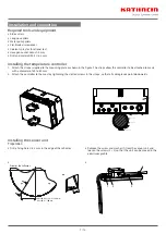
Electrical connection
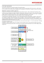
Antenna mast
Tensioning strap
External temerature control
Feed in
Cable from the reflector and
feed system support heating
1. Run the connecting cables for the heating pads, feed system
holder, heating sensor unit and heating pad temperature
sensor along the antenna support to the control unit and
secure with cable ties.
2. Feed the cables into the control unit / connection box from
below through the M16 cable glands (heating pads, feed
system holder heating) and M12 cable glands (temperature
sensors, sensor unit).
3. Feed the mains cable into the control unit through the M32/
M25 cable gland from below.
Before connecting the cables in the control unit, check
the heating for continuity and insulation resistance.
These measurements should also be performed after
replacement of a defective heater. Refer to the oper-
ating instructions for the corresponding reflector
heater for details.
4. The cables are connected as shown in the
“Connection
diagram” on page 11.
Only connect the electrical system to the voltage spec-
ified on the rating plate. Non-compliance can destroy
the heating due to overheating or fire.
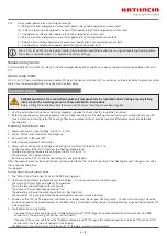
Connecting the earth clamp
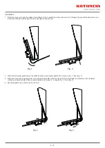
The earth clamp is attached close to the terminal box on the reflector mast as follows:
1. Tension the strap around the mast. Make sure that the strap is securely attached to the antenna mast.
2. Pull the V2A strap through the clamp.
3. Tension the V2A strap with the tension screw.
4. Connect the earth cable to the earth strap clamp.
5. Feed the earth cable through an M12 cable gland in the terminal box.
6. Connect the earth cable to the earth terminal.
➯
This guarantees earthing of the entire electrical system.
M12 3x
M16 5x
M25


