7 / 12
Installation and connection
Required tools and equipment
•
Side cutters
•
Long nose pliers
•
Water pump pliers
•
Flat-bladed screwdriver
•
Coolant spray for functional test
•
Hexagon socket wrench 5 mm
•
Drill and metal drill bit
∅
6.2 mm
Installing the temperature controller
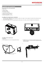
1. Attach the straps supplied to the mounting plate as shown in the figure. The straps allow the controller to be attached to masts
with a diameter of 60 to 85 mm.
2. Attach the controller to the mast by tightening the slotted screws in the straps, so that all cable glands point downwards.
Control unit
Tensioning screw
Mounting plate
Tensioning strap
Antenna mast
Lid
Installing the sensor unit
•
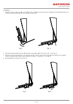
Drill a fixing hole
∅
6.2 mm in the edge of the reflector
•
A
A
A-A
Front of the reflector
X
CAS 120, CAS 124: X = 280 mm
CAS 180: X = 500 mm
•
Remove the screw and washer (1) from the sensor unit and
loosen the screws (2 + 3) so that the unit can be moved in the
aluminium profile
•
1
2
3
4
Preparation


