6 / 12
P34
Relay mode (power relay K1 and signal relay K2)
0 = Relay K2 (active) energised on sensor fault, power relay K1 de-energised on sensor fault
[1] = Relay K2 (passive) de-energised on sensor fault, power relay K1 de-energised on sensor fault
2 = K2 operates as release relay, power relay K1 de-energised on sensor fault
3 = Relay K2 (active) energised on sensor fault, power relay K1 energised on sensor fault
4 = Relay K2 (passive) de-energised on sensor fault, power relay K1 energised on sensor fault
5 = K2 operates as release relay, power relay K1 energised on sensor fault
P34=3, P34=4 and P34=5 is only permitted for frost protection applications and when using self-regulating heating cables.
The values in square brackets [...] represent the factory settings.
Release relay mode
In this mode (P34=2 and P34=5), relay K2 switches independently of P32 and P33 as soon as the actual value lies between P30 and
P31.
Alarm relay mode
(P34 = 0 or 1): If the actual temperature is below P31 when the device is started, P33 is used once as the alarm delay to give the system
more time. In normal operation, P32 is used as the alarm delay.
Commissioning
Reliable operation of the controller requires all components to be installed and started up properly taking
into account the warnings set out in these installation instructions.
Before starting the installation, check the material list to ensure that all parts have been supplied.
1. Use the installation instructions and circuit diagrams supplied to check that the installation is correct.
2. Before connecting the connecting cable in the controller housing, test the heating for continuity and insulation resistance (Ri)
(see installation instructions for the heating). These measurements (Ri) should be repeated after replacement of a defective
heating plate.
Heating functional test
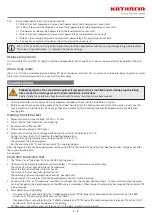
1. Measure the mains input voltage: 230 VAC + 6/- 10%
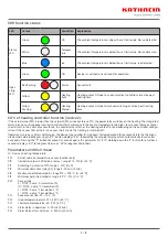
2. Green “Status” and “Operation” LEDS light up
3. Set switch 1S1 to “Manual ON”
4. Yellow “Heating Manual” LED flashes
5. Measure the heating circuit voltage and heating circuit current at terminals X1: 1-10.
During this time, the ELTC-21 monitors the heating temperature.
Change the heating temperature setting on the ELTC-21 to +10°C.
The contactor 1K1 is de-energised.
Set the old value (+40 °C) and the contactor K1 is energised again.
After the measurement has been performed, set the switch 1S1 to the “Auto ON” position. The “Heating Manual” LED goes out after
the set post heating time
has elapsed.
Controller functional test
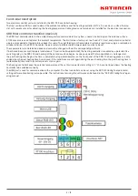
1. The “Status” and “Operation” LEDs on the SRR light up green
2. Cool down the ambient temperature sensor to below + 3°C using iced water or coolant spray.
The status LED must light up white for “Temperature”.
Touch the two rod electrodes with wet hands.
The status LED must now light up blue for “Ice”.
The operating LED must now light up yellow for “Heating Auto”.
The contactor 1K1 is energised and the operating hours counter must be running.
3. As soon as the “Ice” or “Temperature” condition is no longer met, the set post heating time (1 - 10 min) starts running. This value
can be changed on the potentiometer on the SRR using a screwdriver. When the post heating time has elapsed, the contactor 1K1
is de-energised.
4. Fault detection and signalling
- Disconnect the sensor cable from the “Ambient temperature” PT100. (Open the cable connection at terminal 3 on the SRR
control unit). The operating LED flashes red for “Alarm”.
- Disconnect the sensor cable from the “Reflector temperature” PT 100 (open the cable connection at terminal 17 on the ELTC-21
control unit). Fault signal E02 appears in the display.
For both faults, the alarm contact at terminal X1, 11 / 12 opens (closed circuit principle).


