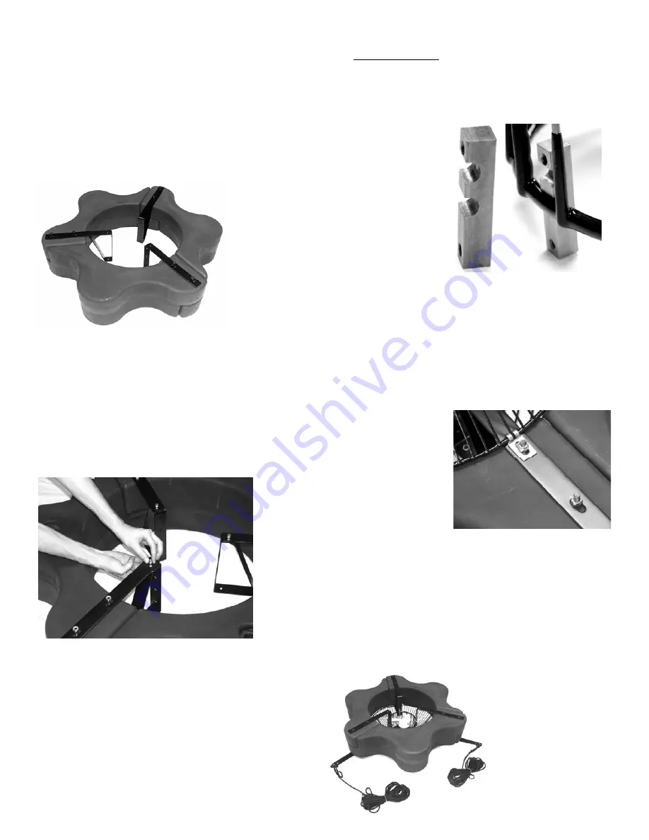
background image

16 

STEP THREE 

Position one Top Float Bracket (Part B2-2)so the bolt 
holes in the bracket align with the bolt holes in the 
two adjoined float sections and insert two 9” Black 
Coated Bolts (Part B2-4) through the assembly.  This 
may require some minor repositioning of the Float 
Sections as you push the bolt all the way through.  

Do 

not force the bolt through.  

Repeat at the remaining 

two joints. 


STEP FOUR 

Turn the assembly upside down and place the Bottom 
Float Brackets (Part B2-3) over the bolts, the ends of 
which should now be extending through the assem-
bly.  Loosely install the six Lock Nuts (Part B2-5)on 
the ends of the bolts 

(do


not tighten).  

Connect the top 

and bottom brackets using three 1/4” x 3/4” Bolts 
(Part B2-7) with three 1/4” Lock Washers (Part B2-8)
and 1/4” Nuts (Part B2-9) and tighten. 


STEP FIVE 

Place the motor assembly (can side up, white propel-
ler down) in the center of the float.  Attach the motor 
to the float using the Unit Mounting Brackets (Part 
B2-6), 1/4”x 3/4” Bolts and 1/4” Lock Washers.  
(This step may require a second person or object 
about 4.5” (11.5cm) tall to support the weight of the 
motor inside the float.  If a support object is used, 
make sure the weight is supported on the cage, not 
the propeller.


For Model 8400EAF, the notch in the center of the 
Unit Mounting Bracket should be positioned over the 
top ring of the cage and should be attached to the 
Float Bracket using the two lowest holes (closest to 
the Lower Bracket) of the Top Float Bracket.  (Please 
refer to photos below.) 


STEP SIX 

(Optional Bottom Screen)


If the optional Bottom Screen (Part B2-10) was pur-
chased, it can now be installed.  Position the Bottom 
Screen over the float so the motor housing (can) 
passes through the large hole in the center of the 
screen.  Remove the center three Lock Nuts from the 
9” Bolts and place the Bottom Screen Clips (Part B2-
11) over the Bolts as shown.  The power cord can be 
slid under the bottom 
screen between the 
float and screen where 
two float sections 
come together before 
the 3/8” Lock Nuts are 
replaced.  Replace the 
three inside Lock Nuts 
and tighten all six 
Lock Nuts. 
 

STEP SEVEN 

Connect the cord and disconnect per instructions on 
page 4-5.   Use the Metal Strain Relief provided.  
This will help keep the cord free of the propeller and 
help prevent damage as well as protect the discon-
nect.  The Aerator is now completely assembled and 
can be installed following the instructions below. 


Summary of Contents for F2400EAF

Page 1: ...luded Tools Needed Pattern Sizes EVFX 2400EJF Assembly Instructions 8400EJF 3 1EJF Parts Included Tools Needed Pattern Sizes 8400EJF 3 1EJF Assembly Instructions EAF and ECF Parts Included Tools Neede...

Page 2: ...in operation It is NEVER recommended to enter the water with the equipment in operation Caution should be used when dealing with any electrical equipment with moving parts NEVER run the unit out of wa...

Page 3: ...are designed and engineered for continuous duty such as on fish farms or other aquacul ture applications or on demand use as needed in a recreational water feature During flotation operation the wate...

Page 4: ...land is orientated with the stepped edge facing the gland nut see picture top of next column STEP THREE Prepare the cable and strip wire ends as shown below STEP FOUR Insert the stripped wire ends int...

Page 5: ...t Kasco does not recommend adding more than 60m of cord to any unit The chart below shows the proper Gland to be used with different cord sizes The measurements are based on the Outside Diameter O D o...

Page 6: ...0EJF FOUNTAIN TOOLS SUPPLIES NEEDED A Anchors or stakes for installing unit 2 B 2 Phillips head screw driver C 240V Electrical Supply near pond on a post D Two 30cm pieces of 2 54cm galvanized pipe fo...

Page 7: ...zzle marked C1 on fin makes use of the collar marked C2 on the top rim and the 3 8 x 4 bolt Linden Display Produces a two tiered display with a center column 1 3 meters tall by 0 7 m wide and an outer...

Page 8: ...1 4 Phillips Pan Head Screws Part C and a 1 4 Flat Washer Part D to secure the float to the motor housing Insert screw with washer through bolt hole in float and into receptacle on the unit Tighten u...

Page 9: ...re the power cord to a molded hole in the float to prevent cord damage if there is no strain relief on the cord If a Strain Relief is present on the cord you may disregard the Nylon Tie On cords with...

Page 10: ...Diagram to Right 1 6 x 1 2 Phillip Pan Head Self Tapping Screw 3 2 3 8 x 4 bolt 1 3 Linden Nozzle 1 4 Redwood Nozzle Y Insert comes installed in 7 1 5 Juniper Nozzle 1 6 Willow Nozzle 1 7 Redwood Spr...

Page 11: ...n nozzle marked L inside one of the fins uses the 3 8 x 4 bolt LINDEN Model HP Height Width 8400EJF 2 4 7 10 4 3 1EJF 3 4 1 9 8 The Willow nozzle marked W on the inside of the cone uses the 3 8 x 4 bo...

Page 12: ...should now be extending through the assem bly Loosely install the six Lock Nuts Part B5 on the ends of the bolts do not tighten yet Connect the top and bottom brackets using three 1 4 x 3 4 Bolts Par...

Page 13: ...talled and seated properly into the nozzle Push the nozzle down over the cone assem bly it may require light taps with a rubber mallet to seat properly Next use the 3 Self Tapping Screws Part D1 provi...

Page 14: ...l 3 D 9 16 14mm 7 16 11mm Nut Driver E 9 16 14cm 7 16 11mm Socket F Adjustable crescent wrench Aerator Parts Included EAF Models A Aerator Unit with cord or stub cord 1 B1 Small Float Ring with two 50...

Page 15: ...the three bolts previously removed with the 3 hooks provided with the Bottom Screen making sure the hook passes through the screen just inside the top support ring of the screen not through the handl...

Page 16: ...e motor inside the float If a support object is used make sure the weight is supported on the cage not the propeller For Model 8400EAF the notch in the center of the Unit Mounting Bracket should be po...

Page 17: ...ired location in the pond lake secure the cord near power source to prevent it from being dragged into the wa ter Anchor the ropes or secure them to the shoreline so the ropes are free of slack but no...

Page 18: ...d two Stainless Steel Lock Washers Part B13 See photo above for orientation STEP FOUR Place one of the three Angle Brackets Part B4 perpendicular to the Base Strap at the front end of the Base Strap O...

Page 19: ...nt or back to the Draw Band itself it is reversi ble Orient the arm of the Draw Band so it aligns with the cord clamp on the cage of the motor housing and is parallel to the Angle Brackets attached in...

Page 20: ...STEP THIRTEEN Float the circulator in the water and position where desired Tie the front Rope to a stake on the shore or weight If a weight is used sink weight in front of unit so rope is taught Circu...

Page 21: ...owever when the wa ter is thrust into the air it is exposed to the colder air temperatures longer and can actually make ice thicker on the pond lake Storage over winter is best in a location that is o...

Page 22: ...n the unit off when it overheats Once the unit has cooled down it will start back up If you are noticing these symptoms the unit should be unplugged immediately because the Thermal Overload will conti...

Page 23: ...Kasco Marine Inc 800 Deere Rd Prescott WI 54021 Phone 715 262 4488 Fax 715 262 4487 www kascomarine com sales kascomarine com service kascomarine com 884150...

Reviews: