background image


kas.com.au 

kas.com.au 

4.


Fingerprint ID  (set previously)  E.g 3 

Controller ID will be set 2550003


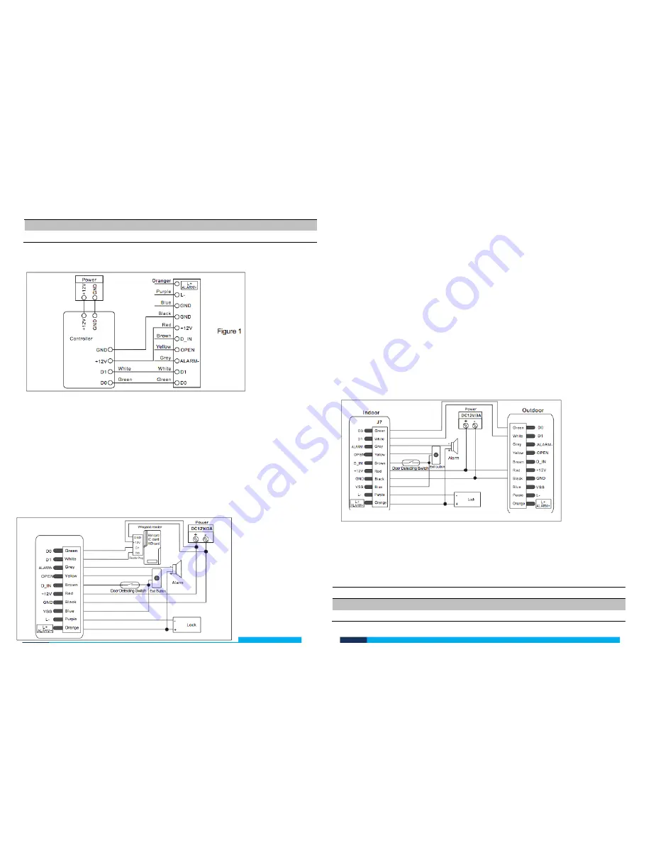
Working as a Slave Reader connecting to Controller Wiring Diagram 


Working as Controller connecting to a Slave Reader 

 
The KAS-322-FP supports Wiegand input. Any card reader, which supports 
Wiegand 26 interface can connect to it as its slave reader, including ID and IC. 
Keycards must be added at the slave reader, not the controller unless an EM card 
reader is used. EM Cards can be added either by slave reader or control. 
 

Working as Controller connecting to a Slave Reader Wiring Diagram 


Using Two Access Controls On One Door 

Two KAS-322-FP can be used on a single door, creating the need for users to be 
verified upon entering and exiting.  
The information on the 2 devices is shared so users can enroll on either device, 
gaining access on both sides of the door. This doubles you current memory to 
6000 users. 
 
Note: The settings, Master code and Master fingerprints for the 2 controls must be 
the same. If they are not the same the controls will act as individual controls and 
you will need to add users on both controls etc. 


Using Two Access Controls On One Door Wiring Diagram 


Two Devices Interconnected & Interlocking- Two Doors  

This high security feature is designed for areas that have 2 doors accessing the 
same area eg, banks, safe rooms. 
The interlocked function will work on either door. One door must be locked for the 
other to unlock and open. 

1.


Scan Keycard or fingerprint on first access control 

2.


Enter first door 

3.


Shut first door 

KAS

-320

-FP


KAS-320-FP 

KAS-320-FP Controller 1 

KAS-320-FP Controller 2 

Summary of Contents for KSS-320-FK

Page 1: ...kas com au kas com au For orders enquiries and technical support please call 1300 939 669 tech kas com au www KAS com au User Guide KSS 320 FK Access Control...

Page 2: ...ings 6 Remove ALL Users 6 Setting Facility Code 6 Setting Lock Style and Door relay time 6 Setting Door Open Detection 7 Setting Security Status 7 Setting Two Devices to be contacted 7 Setting Alarm s...

Page 3: ...screws and 1 hole for the cable Fix the back cover firmly on the wall with 4 flathead screwsprovided Thread the cable through the cable hole Attach the device face to the back cover Sounds and Lighti...

Page 4: ...ND Request to Exit Button Door Contact Black GND Negative Regulated Power Input Red 12V 12V DC Positive Regulated Power Input Brown D IN Door Contact Yellow OPEN Request to Exit Button Grey Alarm Alar...

Page 5: ...Add Card over face of control 2 Enter 1st users fingerprint twice Note lift finger after first scan and place back on scanner for second scan or Scan new users Keycard 3 To add more users Repeat step...

Page 6: ...ger Delete fingerprints 1 Enter programing mode 2 Press 1 1 3 Scan fingerprint twice This will be the ADD Fingerprint 4 Press 2 5 Scan another finger twice This will be the DELETE fingerprint 6 Press...

Page 7: ...Select Status Press 7 0 Normal Status Press 7 1 Lock on Status Press 7 2 Alarm Status 3 Press Setting Two Devices to be contacted Disabled Factory default 1 Enter programming mode 2 Press 8 0 Disabled...

Page 8: ...erified upon entering and exiting The information on the 2 devices is shared so users can enroll on either device gaining access on both sides of the door This doubles you current memory to 6000 users...

Page 9: ...com au 4 Scan Keycard or fingerprint on second access control 5 Enter second door 6 Shut second door Two Devices Interconnected Interlocking Two Doors Wiring Diagram KAS 320 FP Controller 1 KAS 320 F...

Reviews: