background image

9.800-083.0  •  Rev. 01/08

11


PRESSURE 

W

ASHER


OPERA

T

OR’S MANU

AL
  

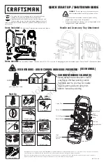
SHUTTING dOWN ANd CleAN-UP

STe P  1:  Remove  detergent  suc-
tion  tube  from  container  and  insert 
into one gallon of fresh water. Slide 
nozzle forward for low pressure or to 
connect black detergent nozzle into 
wand  quick  coupler.  Pull  trigger  on 
spray gun and siphon water for one 
minute.

STeP 2:  Turn off the engine.

STeP 3:  Turn off wa-
ter supply.

STeP 5:  Disconnect the gar-
den hose from the water inlet 
on the machine.

STeP  6:   Disconnect  the  high 
pressure hose from high pres-
sure outlet.

S T e P   7 :   E n g a g e 
the  spray  gun  safety 
lock.

STe P 4: Press trigger 
to release water pres-
sure.

CAUTION: Always store your pressure washer in a 
location where the temperature will not fall below 
32°F (0°C). The pump in this machine is susceptible 
to permanent damage if frozen. FREEZE DAMAGE 
IS NOT COVERED BY WARRANTY.
  1.  Stop the pressure washer, squeeze spray gun trig-

ger to release pressure.

  2.  Detach water supply hose and high pressure hose.
  3.  Turn on the machine for a few seconds, until  re-

maining water exits. Turn engine off immediately.

  4.  Drain the gas and oil from the engine.
  5.  Do  not  allow  high  pressure  hose  to  become 

kinked.

  6.  Store the machine and accessories in a room which 

does not reach freezing temperatures.

CAUTION: Failure to follow the above directions will 
result in damage to your pressure washer.
When the pressure washer is not being operated or is 
being  stored  for  more  than  one  month,  follow  these 
instructions:
  1.  Replenish engine oil to upper level.
  2.  Drain gasoline from fuel tank, fuel line, fuel valve 

and carburetor.

  3.  Pour about one teaspoon of engine oil through the 

spark plug hole, pull the starter grip several times 
and  replace  the  plug.  Then  pull  the  starter  grip 

slowly until you feel increased pressure which in-
dicates the piston is on its compression stroke and 
leave it in that position. This closes both the intake 
and exhaust valves to prevent rusting of cylinder.

  4.  Cover the pressure washer and store in a clean, 

dry place that is well ventilated away from open 
flame  or sparks. NOTe : The use of a fuel additive, 
such as STA-BIL

®

, or an equivalent, will minimize 

the formulation of fuel deposits during shortage. 
Such additives may be added to the gasoline in 
the fuel tank of the engine, or to the gasoline in a 
storage container.

After extended Storage

CAUTION: Prior to restarting, thaw out any 
possible ice from pressure washer hoses, 
spray gun or wand.

engine Maintenance

During the winter months, rare atmospheric conditions 
may develop which will cause an icing condition in the 
carburetor. If this develops, the engine may run rough, 
lose power and may stall. This temporary condition can 
be overcome by deflecting some of the hot air from the 
engine over the carburetor area.  NOTe:  Refer to the 
engine manufacturer's manual for service and main-
tenance of the engine.

STOrAGe

Pump Water 

Inlet

High Pressure 

Outlet

Safety latch

On-Off
Switch

Summary of Contents for BG-282037

Page 1: ...5 151 0 BG 252737 HD 3 0 30 Pb 1 575 152 0 BG 303037 HD 3 7 35 Pb 1 575 154 0 BG 373537 HD 3 0 40 Pb 1 575 155 0 BG 304037 HD 3 5 32 Pb 1 575 156 0 BG 353237 OPERATOR S MANUAL To locate your local K r...

Page 2: ......

Page 3: ...sembly Instructions 7 Operating Instructions 8 9 Detergents Cleaning Techniques 10 Shut Down and Clean Up 11 Storage 11 Troubleshooting 12 Adjusting Unloader Valves 12 Preventative Maintenance 13 Oil...

Page 4: ...ay alert watch what you are doing 4 All installations must comply with local codes Contact your electrician plumber utility company or the selling distributor for specific details WArNING risk of asph...

Page 5: ...caution when oper ating Do not direct discharge stream at people or severe in jury or death will result 13 Never make adjustments on machine while in op eration 14 Be certain all quick coupler fitting...

Page 6: ...the spray gun High Pressure Hose Connect one end to water pump discharge nipple detergent injector nipple and the other end to spray gun Note If trigger on spray gun is released for more than 1 2 min...

Page 7: ...ks Pull the nozzle to make sure it is secure STEP 7 Connect high pressure hose to pump discharge fitting Push coupler collar forward until secure STEP 5 Pull the spring loaded collar of the wand coupl...

Page 8: ...eck pump oil level by using dipstick or observe oil level in oil window if equipped Use 30 wt non detergent oil STEP 5 Move the fuel shut off valve to the On posi tion When the engine is not in use le...

Page 9: ...ast position CAUTION Small engines may kick back Do not hold pull starter grip tightly in hand operating instr uctions cont The five color coded quick connect nozzles provide a wide array of spray wid...

Page 10: ...cleaning tips Pre rinse cleaning surface with fresh water Place de tergent suction tube directly into cleaning solution and apply to surface at low pressure for best results limit your work area to se...

Page 11: ...the pressure washer is not being operated or is being stored for more than one month follow these instructions 1 Replenish engine oil to upper level 2 Drain gasoline from fuel tank fuel line fuel valv...

Page 12: ...lace as needed Slow engine RPM Set engine speed at proper specifications Pump sucking air Check water supply and possibility of air seepage Valves sticking Check and clean or replace if necessary Unlo...

Page 13: ...ce Regular preventative maintenance will add many hours to the life of your pressure washer Perform maintenance more often under severe conditions Maintenance Operation Every 8 Hrs or Daily 25 Hrs or...

Page 14: ...150 0 1 575 151 0 27 58 42 43 44 45 41 59 28 30 31 29 6 62 62 6 5 4 3 2 1 62 56 57 11 12 17 40 16 11 10 13 14 20 21 19 60 18 54 23 22 36 37 59 36 25 52 51 50 49 53 55 48 36 15 26 36 47 39 38 7 24 36...

Page 15: ...2 18 9 802 782 0 Collar 5 8 Bore Shaft 3010 2 19 9 802 270 0 Wheel Tire Assembly 4 Steel Rim w Tube 2 20 9 803 124 0 Frame Assy Small Black 1 21 9 802 712 0 Bolt 5 16 x 1 3 4 NC Carriage Zinc 4 22 9 8...

Page 16: ...1 55 9 800 006 0 Label Hot Caliente w Arrows Warning 1 56 9 800 014 0 Label Intended For Outdoor Use 1 57 9 800 034 0 Label Clear Lexan 2 1 4 x 4 1 2 1 58 9 802 287 0 Nozzle SAQCMEG 0003 0 Red 151 0...

Page 17: ...0 18 19 10 11 12 13 11 12 17 14 16 32 20 28 30 6 29 31 1 60 59 59 2 3 4 6 5 58 41 42 43 46 44 40 39 38 33 37 33 36 45 35 50 52 26 27 25 61 62 55 12 15 48 53 51 49 24 57 56 60 23 22 54 12 21 11 7 64 3...

Page 18: ...3 115 0 Frame Assy Large Black 1 21 9 802 712 0 Bolt 5 16 x 1 3 4 NC Carriage Zinc 4 22 9 802 776 0 Nut 5 16 ESNA NC 4 23 9 802 804 0 Washer 5 16 Flat SAE 4 24 8 911 226 0 Axle 5 8 x 27 L 1 25 9 803 1...

Page 19: ...Intended For Outdoor Use 1 57 9 800 034 0 Label Clear Lexan 2 1 4 x 4 1 2 1 58 9 802 291 0 Nozzle SAQCMEG 0003 5 Red 152 0 1 9 802 292 0 Nozzle SAQCMEG 1503 5 Yellow 152 0 1 9 802 293 0 Nozzle SAQCME...

Page 20: ...02 369 0 1 575 151 0 2 5 2700 3 0 KD3030 9 803 825 0 9 803 899 0 GX200 6 5hp 9 802 317 0 BK80H 9 802 380 0 1 575 152 0 3 0 3000 3 5 KD3030 9 803 825 0 9 803 899 0 GX270 9hp 9 802 315 0 2BK80 9 802 389...

Page 21: ...1 9 803 896 0 1 575 151 0 24MM 9 802 402 0 BK36H 9 802 379 0 HX3 4 9 803 897 0 BX32 1 9 802 413 0 1 575 152 0 24MM 9 802 402 0 2BK40H 9 802 384 0 HX1 9 802 398 0 BX38 2 9 802 417 0 1 575 154 0 24MM 9...

Page 22: ...1 3 9 802 164 0 Coupler 1 4 Female Brass 1 4 Nozzle See Breakdown for Part Numbers 5 8 739 125 0 Hose 3 8 x 50 1 Wire Tuff Flex 150 0 151 0 152 0 1 8 739 203 0 Hose 3 8 x 50 2 Wire Tuff Flex 154 0 1...

Page 23: ...Intermed Ring 18mm 4035 3 9 803 173 0 Intermed Ring 20mm 4030 5030 3 8 717 178 0 Intermediate Ring 15mm 3540 3 item Par t no Description QTY 9 9 802 926 0 Brass Plug 1 2 1 10 9 803 199 0 Copper Washer...

Page 24: ...ase Cover 1 49 9 803 906 0 O Ring 1 78 x 14 1 50 9 803 202 0 Sight Glass 3 4 1 51 9 802 939 0 Cover Screw 5 52 8 730 836 0 Bach Ring 1 2 4035H 3 Available in kit See below Not Shown Repair kit number...

Page 25: ...ing 1 11 9 803 947 0 O Ring 1 78 x 15 54 6 12 See Kits Below Valve Assembly 6 13 9 803 948 0 O Ring 2 62 x 18 77 6 item Par t no Description QTY 14 9 803 949 0 Valve Plug 6 15 9 803 950 0 Copper Washe...

Page 26: ...g Rod 3 42 9 803 218 0 Spring Washer 6 43 9 803 967 0 Connecting Rod Screw 6 44 9 803 202 0 Sight Glass 1 45 9 803 197 0 Gasket 1 46 9 803 968 0 Crankcase Cover 1 47 9 803 969 0O Ring 2 62 x 107 6 2 A...

Page 27: ...O Ring A 1 10 9 803 911 0 Connector 1 11 9 803 912 0 Teflon Ring A 1 12 9 803 913 0 Stem C 1 13 9 803 914 0 Connector Female 1 14 9 803 191 0 O Ring A B 1 ITEM Par t description Kit qty 15 9 803 916...

Page 28: ......

Page 29: ...tning strikes 7 Defects caused by water sediments rust corrosion thermal expansion scale deposits or a contaminated water supply such as water in the unit with chloride content higher than that of 80...

Page 30: ...Form 9 800 083 0 Revised 01 08 Printed in U S A...

Reviews: