-
3
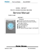
The water flows back from the swimmer
tank to the suction side of the pump. The
water level in the swimmer tank is kept con-
stant by the swimmer valve. In case of fail-
ure of the swimmer valve, the water exits
via the overflow. If the water supply is dis-
turbed, the lack of water fuse will send an
error message to the controls.
The electric engine will drive the crankshaft
pump. The pump transports the water un-
der high pressure to the pressure side.
The high-pressure water reaches the high-
pressure output via the overflow valve and
the pressure sensor. After that, there will be
the high-pressure network of the operator.
Remaining water will be routed back to the
suction side of the pump by the overflow
valve. If all consumer loads have been
switched off, the overflow valve will switch
to circulation. If the pressure at the output
exceeds the maximum operating pressure
at the output, the safety valve will open.
– The appliance will be switched to
READY mode by activating the release
switch. The indicator lamp for opera-
tional readiness lights up. If the pres-
sure in the systems sinks below the de-
termined switch-on point due to the
opening of a hand spray gun, the high-
pressure pump will be switched on.
– If the flow switch in the high-pressure
line trips after closing all hand spray
guns while the pump is running, the
pump is switched off again with a delay
of 10 seconds (HDC 20/8) or 30 sec-
onds (HDC 20/16).
– If the system is ready and the high-
pressure is not turned on, a timer is
started, which will reset the readiness of
the unit after 6 hours. The operation
readiness indicator lamp goes off.
Safety devices serve for the protection of
the user and must not be put out of opera-
tion or bypassed with respect to their func-
tion.
The safety mechanism against lack of wa-
ter prevents the high pressure pump from
being switched on when there is no water.
The temperature sensor switches off the
appliance as soon as the water tempera-
ture is too high.
The winding protection contact in the motor
winding of the pump drive switches off the
engine when there is a thermal overload.
– The safety valve opens when the over-
flow valve is defective.
– The safety valve is set by the manufac-
turer and sealed. Setting only by cus-
tomer service.
– If the hand spray gun is closed, the
overflow valve opens and the entire wa-
ter volume will flow back to the pump
suction side.
– If the hand spray gun is closed, the
pump is switched off via the flow switch
after a stopping time of 10 seconds
(HDC 20/8) or 30 seconds (HDC 20/16).
If the hand spray gun is opened again, the
pressure switch switches on the pump via
the pressure sensor.
Water inlet
Pumps
High pressure side
Pressure regulation
Controls
Safety Devices
Safety mechanism against lack of
water in swimmer tank
Temperature sensor
Winding protection contact
Safety valve
Overflow valve with flow switch
Pressure sensor
19
EN
Summary of Contents for 1.509-501.0
Page 2: ...2...
Page 159: ...3 10 HDC 20 8 30 HDC 20 16 6 10 HDC 20 8 30 HDC 20 16 159 EL...
Page 161: ...5 30 cm K rcher 0 1 30 6 0 161 EL...
Page 163: ...7 HDC 20 16 A DN 15 M22x1 5 B 3 4 580 860 820 615 163 EL...
Page 164: ...8 40 3 6 288 016 200 3 5 40 mm 28 mm 2 Nm 29 mm 6 Nm 500 1 6 288 016 0 1000 40 mm 164 EL...
Page 165: ...9 K rcher 1 7 01 02 03 04 1 30 05 2 06 07 08 ON 165 EL...
Page 166: ...10 0 01 02 03 04 05 06 07 166 EL...
Page 170: ...14 170 EL...
Page 187: ...3 10 HDC 20 8 30 HDC 20 16 6 10 HDC 20 8 30 HDC 20 16 187 RU...
Page 189: ...5 30 Karcher 0 1 30 6 0 189 RU...
Page 191: ...7 HDC 20 16 A DN 15 M22x1 5 B 3 4 580 860 820 615 191 RU...
Page 192: ...8 40 3 6 288 016 200 3 5 40 28 2 29 6 500 1 6 288 016 0 1000 40 192 RU...
Page 193: ...9 Karcher 1 7 01 02 03 04 1 30 05 2 06 07 08 EIN 193 RU...
Page 194: ...10 0 01 02 03 04 05 06 07 194 RU...
Page 198: ...14 198 RU...
Page 313: ...3 10 HDC 20 8 30 HDC 20 16 6 10 HDC 20 8 30 HDC 20 16 313 BG...
Page 315: ...5 30 cm K rcher 0 1 30 6 0 315 BG...
Page 317: ...7 HD 20 16 A DN 15 M22x1 5 B 3 4 580 860 820 615 317 BG...
Page 318: ...8 T o 40 3 6 288 016 200 3 5 40 mm 28 2 Nm 29 6 Nm 500 1 6 288 016 0 1000 40 mm 318 BG...
Page 319: ...9 K rcher 1 7 01 02 03 04 1 30 05 2 06 07 08 319 BG...
Page 320: ...10 0 01 02 03 04 05 06 07 320 BG...
Page 324: ...14 324 BG...
Page 369: ...3 10 HDC 20 8 30 HDC 20 16 6 10 HDC 20 8 30 HDC 20 16 369 UK...
Page 371: ...5 30 K rcher 0 1 30 6 0 371 UK...
Page 373: ...7 HDC 20 16 A DN 15 M22x1 5 B 3 4 580 860 820 615 373 UK...
Page 374: ...8 40 3 6 288 016 200 3 5 40 28 2 29 6 500 1 6 288 016 0 1000 40 374 UK...
Page 375: ...9 K rcher 1 7 01 02 03 04 1 30 05 2 06 07 08 375 UK...
Page 376: ...10 0 01 02 03 04 05 06 07 376 UK...
Page 380: ...14 380 UK...
Page 381: ......
Page 382: ......
Page 383: ......
Page 384: ...http www kaercher com dealersearch...