15
Service and Repair Manual
Model 1400KV/1400BV
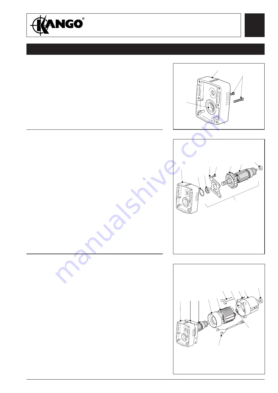
ASSEMBLY
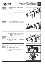
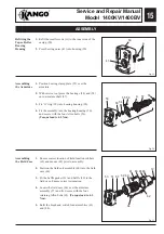
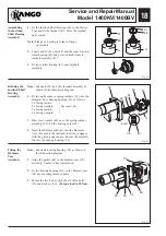
Fig. 19
Fig. 20
1.
Refit the small screws (A) to the inner side of the
casing (50).
2.
Press bearing outer (41) into housing (50).
Refitting the
Taper Roller
Bearing
Housing
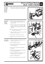
1.
Position bearing clamp plate (55) over the
armature.
2.
With service tool press the bearings (54) and (58)
onto armature shaft (57).
3.
Fit ‘O’ ring (53) into bearing housing (50).
4.
Fit the assembly into the bearing housing (50)
and secure with the four Allen bolts (56).
(Torque load to 4.5 Nm).
Assembling
the Armature
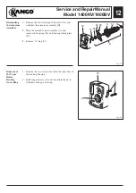
Assembling
the Field Case
1.
Ensure correct location of field location rubbers
(63) and mount (62) prior to assembly.
2.
Position the field coil assembly (60) into the field
case (66).
3.
Fit the baffle gasket (51) and baffle (59) to the
field case. Ensure correct orientation.
4.
Locate the field case (66) over the armature
assembly (57) and fit. Secure with the four
retaining Allen bolts (65).
(Torque load to 4.5
Nm).
5.
Refit the brush and switch lead assemblies (61)
and (84).
50
A
B
53
57
A
56
55
54
50
66
65
61
60
59
51
50
84
62
72
57
63
Fig. 21
58
41
Summary of Contents for 1400 Series
Page 1: ......


