10
Service and Repair Manual
Model 1400KV/1400BV
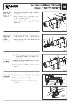
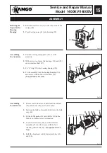
Fig. 13
Fig. 10
Fig. 11
Fig. 12
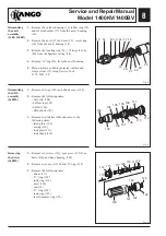
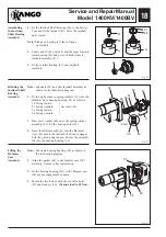
1.
Using a wooden hammer shaft, gently push the
striker assembly (23), from the hammer case (34).
2.
Remove and discard the striker bearing clips (24)
and the seal (25).
Removal and
Dismantling
of the
Striker
Assembly
1.
Pull the piston assembly (45) from the hammer
casing (34).
2.
Remove and discard the bearing clip (44) and
withdraw the gudgeon pin (43).
3.
Remove and discard the nu-lip seal (42) from the
piston (45).
Removal and
Dismantling
of the Piston
Assembly
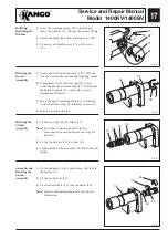
Removal of
the Barrel
Assembly
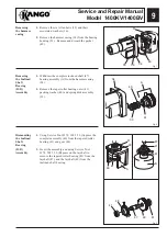
1.
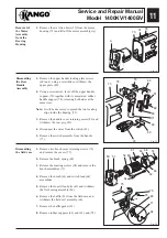
Remove the three retaining screws (31) and the
barrel retainer (38).
2.
Press the barrel assembly (37) , from the hammer
case (34).
Note:
The following procedure is carried out only if
the barrel is damaged or worn, and is to be
replaced.
45
44
42
34
43
23
24
25
34
31
38
34
37
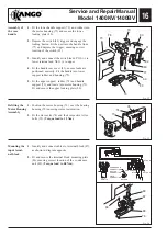
Removal of
the Carbon
Brushes
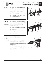
1.
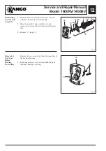
Remove two screws (76) and mounting plate (86).
2.
Disconnect condensor unit (89).
3.
Identify and disconnect cables from terminal
block (87).
DETAIL A
DETAIL B
CONDENSOR
CONDENSOR
CONNECTION
SWITCH
CONNECTION
FIELD
CONNECTION
BLUE
DETAIL B
DETAIL A
SWITCH LEADS
SWITCH LEADS
89
87
86
76
69
Summary of Contents for 1400 Series
Page 1: ......


