7
Service and Repair Manual
Model 1400KV/1400BV
DISMANTLING
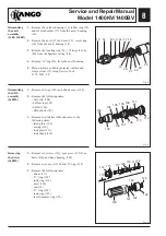
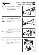
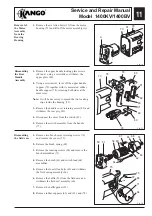
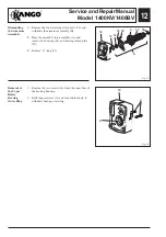
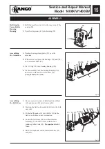
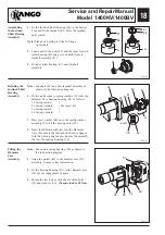
Fig. 1
Fig. 2
Fig. 3
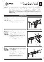
Important!
Before carrying out any repairs, the hammer should be checked for electrical safety and for mechanical
performance. For electrical safety the hammer should be placed on a non-conductive surface which is
either of a wooden construction (with the mains supply disconnected) which contains no metal parts or a
bench which is insulated by a rubber mat. The hammer should then be checked by high voltage flash
testing. On completion of dismantling procedure all electrical components should then be checked for
electrical safety. The hammer should
ONLY
be checked for hammer performance if the unit passes the
electrical safety test.
Removing the
tool locking
mechanism
(1400, 1400B)
1.
Using a hammer and suitable drift, remove the
latch bar (4).
2.
Remove and retain the latch end retainer (7),
spring (6) and cover (5).
Removing
the nosepiece
(1400, 1400B)
1.
Remove the six Allen retaining screws (35) from
the nose piece (8).
2.
Remove the nosepiece assembly (8).
3.
Remove the six allen screws (35) from the anvil
housing (14) and remove anvil housing (14).
4.
Remove and discard O-rings (3) & (11).
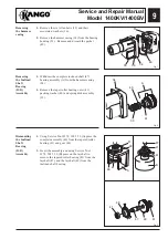
Removing the
front handle
mechanism
(1400, 1400B)
1.
Remove the circlip (1), knob (28), and retaining
screw (27) together with the associated washer
(29).
2.
Remove the front handle (30), nose cap (2) and
strap casting (26).
Warning: Hold strap casting (26) whilst
removing nose cap (2).
4
8
5 6 7
1
2
28
26
27
30
3
35 8 11
14
34
29
35
Summary of Contents for 1400 Series
Page 1: ......


