background image

KaCool D

02.02.2017

34

Installation and Connection

Accessories: External condensation pump

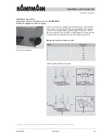
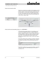
Accessories: External air outlets


Up to two air pipes can be connected to the cassettes to supply 
adjacent rooms (e.g. changing rooms) with conditioned air 
from the cassette. Two pre-punched openings with a diameter 
of 150 mm have to be removed on the sides of the cassette 
to which on-site 

fl

 anges have to be 

fi

 tted. Insulated air ducts 

and outlets can be connected to them. Seal the respective air 
outlets with an adhesive tape.

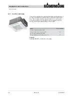
Accessories: External condensation pump, art. no. 325007000410


If the condensation pumps installed in the cassettes do not 
reach the max. head (650 mm), you can use an additional 
external condensation pump. This can be 

fi

 tted adjacent to or 

onto the cassette. To do this, insert the condensation hose of 
the cassette into the collecting vessel of the external pump. 
Please refer to the supplementary lea

fl

 et relating to the 

external condensation pump for further technical data about 
the pump.  


The power supply must be provided via a separate supply line. 
The fault alarm contact must be integrated in the controls of 
the cooling valve and this must be switched off in case of a 
fault.  


The external condensation pump produces higher noise levels. 
This must be taken into consideration when choosing the 
installation site! 

Air distribution

Primary air 

fl

 ow

Recirculating air

Connection dimensions

Model 1–3

Model 4–6

150 mm

180 mm

Technical data:

Max. head:

4.6 Meter

Maximum number of connectable cassettes: 2 no.

2 Stück

Summary of Contents for KaCool D 1

Page 1: ...KaCool D Ceiling Cassette Installation and Operating Instructions Keep these instructions in a safe place for future use I 500 01 17 GB SAP Nr 1216770...

Page 2: ...Kampmann co uk KaCool D Kampmann GmbH Friedrich Ebert Str 128 130 49811 Lingen Ems Germany T 49 591 7108 660 F 49 591 7108 173 E export kampmann de W Kampmann eu...

Page 3: ...ective Equipment 11 3 Technical Data 12 3 1 Main Dimensions 12 3 2 Connection Dimensions 13 3 3 Weights 14 3 4 Connected Loads 14 3 5 Operating Data 15 3 6 Specification Plates 16 3 6 1 Specification...

Page 4: ...hecks 51 7 2 Venting the Heat Exchanger 52 7 3 Switching on the Unit 52 8 Maintenance 53 8 1 Preventing the Unit from being Switched on Again 53 8 2 Maintenance Schedule 54 8 3 Maintenance Work 55 8 3...

Page 5: ...ent prevention regulations and general safety conditions for the application are also applicable Illustrations in these instructions are intended to facilitate basic understanding and may deviate from...

Page 6: ...technical information We are also always interested in information and experiences resulting from the use of the unit and that may be valuable for the improvement of our products Marking Explanation...

Page 7: ...s about the individual life cycles 2 1 Intended Use Correct and proper use is also deemed to include observing all the information in these instructions Any use over and above the intended use or any...

Page 8: ...containing high temperature gases Never operate the unit in an aggressive or corrosive atmosphere such as sea air Never operate the unit above electrical equipment such as switch cabinets computers o...

Page 9: ...ration of the unit The operator must clearly regulate and specify the responsibilities for installation operation troubleshooting maintenance and cleaning The operator must ensure that all people hand...

Page 10: ...act details 2 5 Personnel Requirements 2 5 1 Qualifications Only people who are expected to perform their work reliably are allowed People whose reactions are influenced for example by drugs alcohol o...

Page 11: ...safety hazards and health risks at work The accident prevention regulations applicable at the location in which the unit is operated always apply If necessary the personnel must wear the personal pro...

Page 12: ...ld water inlet 4 Cold water outlet 2 Model 1 3 dimensions in mm Unit size Model 1 3 Condensation connection 1 2 Connections without valve kit Water inlet outlet 2 pipe Inches 3 4 Water inlet outlet 4...

Page 13: ...pipe cooling Inches 3 4 Water inlet outlet 4 pipe heating Inches 1 2 Connections with valve kit Water inlet outlet 2 pipe Inches 1 Water inlet outlet 4 pipe cooling Inches 1 Water inlet outlet 4 pipe...

Page 14: ...urrent consumption A 0 25 0 40 0 70 0 40 1 10 operating limits water temperature min max C 5 80 air inlet temperature min max C 15 40 air humidity min max 15 75 operating pressure max bar 8 max glycol...

Page 15: ...4 36 24 44 32 50 24 39 25 44 25 49 Min max sound power level dB A 33 45 33 53 41 59 33 48 34 53 34 58 EC fans 2 pipe model Min max cooling output 1 W 1840 2750 2240 4330 2560 5020 4210 6330 5290 10750...

Page 16: ...ting plate Technical Data Specification plate 3 6 Specification Plates 3 6 1 Specification Plate for Basic Unit The specification plate is located on the electrical housing of the basic unit and conta...

Page 17: ...valves 003251173036 Float switch for condensation pump 003251173037 Condensation pump 003251173036 Mounting bracket fixing for cassette 4 no 003251173059 AC fan model Fan motor 003251172596 003251172...

Page 18: ...Design and Function 4 1 Overview 1 2 4 5 3 Punched opening for optional fresh air connection Punched opening for external air outlet Compact basic housing Stylish casing Electrical control box 3 9 5 1...

Page 19: ...c Easy to clean 7 Air filter Simple to remove Easy to clean 8 Air intake grille Large free cross section to minimise pressure losses 9 Hydraulic connections For CHW LPHW and drainage of condensation V...

Page 20: ...in the exchanger depending on the temperature at which the medium flows through the heat exchanger The air passes through the outlet air slats into the room The outlet air slats can be manually adjus...

Page 21: ...trol 325007014122 2 way valve kit 2 pipe system 230 V Open shut Model 4 6 2 Pipe without KaControl 325007022110 24 V Open shut Model 4 6 2 Pipe with KaControl 325007022112 3 way valve kit 2 pipe syste...

Page 22: ...2 8 2 8 50 50 3 4 3 4 4 6 2 Pipe 5 2 60 1 4 Pipe 4 5 2 5 60 50 1 3 4 3 way valve 1 3 2 Pipe 2 5 50 3 4 4 Pipe 5 2 2 8 50 50 3 4 3 4 4 6 2 Pipe 4 5 50 1 4 Pipe 4 5 2 5 50 50 1 3 4 Valve kit Thermoelect...

Page 23: ...d hold the basic housing to lift it not the valves Use suitable transport aids for transport to prevent health related injuries and damage to the units NOTE Property damage due to inappropriate transp...

Page 24: ...ousing Delivery depending on the model ordered Basic housing Basic housing Fixing materials Condensation tray valves Instructions wiring diagram Stylish casing Casing Fixing materials Valve kit Connec...

Page 25: ...mage up until installation Therefore do not destroy the packaging and only remove it just before the installation Handling packaging materials Dispose of packaging material in accordance with the appl...

Page 26: ...ting into service 5 5 Storage Storing the packages Store the packages under the following conditions Do not store outdoors Store in a dry and dust free place Do not expose to aggressive media Keep awa...

Page 27: ...ions for drilling work to install the unit are positioned away from electrical cables or pipes Adequately dimensioned connections for the water supply and drainage are available on site Chapter 3 Tech...

Page 28: ...selecting the cassette determine the optimum position in the room observe the throw data see technical catalogue In addition ensure that draughts are minimised when selecting the position If more tha...

Page 29: ...rawlplugs for fixing the unit Then attach the rawlplugs and for example the threaded rods Fix the mounting brackets supplied with the delivery for the ceiling cassette at an appropriate height The mo...

Page 30: ...n site can then be connected to the valve kit Establish a flexible connection e g using reinforced hoses In any case avoid tensions and vibrations in the pipe system from transferring to the ceiling c...

Page 31: ...ssible but at least 30 cm above the highest point of the condensation line The venting should protect condensation from escaping The riser must be positioned vertically directly on the cassette in an...

Page 32: ...KaCool D 02 02 2017 32 Installation and Connection Installation Casing Installation Casing...

Page 33: ...rs of the ceiling cassette This enables rooms to be supplied with a percentage of fresh air The air has to be cleaned on site with an appropriate air filter and be routed to the cassette at a minimum...

Page 34: ...m you can use an additional external condensation pump This can be fitted adjacent to or onto the cassette To do this insert the condensation hose of the cassette into the collecting vessel of the ext...

Page 35: ...he electric motors on site Lay control lines separately from supply lines Use CAT5 AWG 23 for example or similar as data cables Connect wiring in series star wiring is not permitted Electrical connect...

Page 36: ...he electrical junction box This is located on the opposite side to the unit s water connection Refer to the respective wiring diagram for the wiring which varies depending on the model Example 3250062...

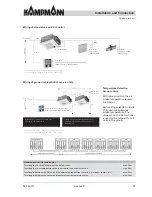
Page 37: ...ling valve has to be routed via the condensation alarm The valve has to be closed when the contact changes to fault AC fans electromechanical model Stand alone unit on site control EC fans electromech...

Page 38: ...P switch 9 D2 D1 CF input External On Off Input CF can be used for example to integrate a window contact or presence detector Remove jumper MC1 if the contact is used Output D0 can be used to pass the...

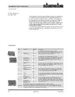
Page 39: ...d OFF 4 Sensor T3 only heating mode ON If sensor T3 is enabled you can decide in which operating modes the control function is enabled using DIP 4 Cooling mode below 20 C starts above 24 C stops Heati...

Page 40: ...s DIP Function Position Description 10 Slave unit ON All slave units are set to ON the master unit is set to OFF Master unit OFF Changeover sensor A sensor T2 must be installed before the cassette and...

Page 41: ...mounted and fixed to the cassette the plug of the receiver can be connected to the PCB Infra red transmitter remote control The enclosed batteries 2x AAA 1 5 V must be inserted into the back of the r...

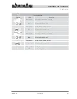
Page 42: ...the clock Save with On Send On Send Save the changed data Increase the set values e g temperature Reduce the set values e g temperature Priority Display Speed Set value Priority Low fan speed low air...

Page 43: ...lay Press Set the desired hour of time Press Select 1x Confirm the hour change to minute Press Set the desired minute of time Press Select 1x Show Program Stop on the display Press Set the desired hou...

Page 44: ...signal on input AI2 GND and AI3 GND see separate KaControl instructions Control via a potentiometer 0 100 kOhm ON 3 Clip on sensor fitted ON The clip on sensor is available as an accessory and can be...

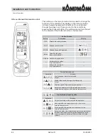
Page 45: ...nstallation Operating unit KaController terminals DIP switch setting KaController DIP switch no 1 ON DIP switch no 2 OFF Installation Dismantling Wiring Connect the KaController to the nearest KaCool...

Page 46: ...lty control sensor A13 Room frost protection A14 Condensation alarm A15 General alarm A16 Faulty AI1 AI2 or AI3 sensor A17 Unit frost protection A18 Faulty EEPROM A19 Offline slave in CAN bus network...

Page 47: ...t If you wish you can separately measure the temperature for each unit via a room or air intake sensor Temperature detection Group control With group control the air intake temperature is used for con...

Page 48: ...DIP switches on all CANbus cards in a control circuit identically DIP switches on the rear of the CAN bus card DIP1 ON DIP2 OFF DIP3 OFF DIP4 OFF DIP5 OFF DIP6 OFF DIP7 OFF DIP8 ON DIP9 OFF DIP10 OFF...

Page 49: ...n be called up with both operating units the buttons offer the option of a shortcut to a few functions 1 2 3 4 5 6 7 1 5 No Description 1 Display to show the set operating mode 2 Ceiling cassette On O...

Page 50: ...Fan speed Change by pressing the side fan button or using the navigator To do this press the navigator once briefly Turning the navigator to the left reduces the desired speed and turning it to the r...

Page 51: ...en correctly installed Note the permissible fitting position of the actuators Have all valves and actuators been fitted correctly Are the shut off valves on site open Condensation drain only for units...

Page 52: ...g spray water Then open the vent screw s Close the vent screw when no air and only water is still escaping 7 3 Switching on the Unit Switch on the mains power supply Put the unit into operation using...

Page 53: ...s are installed and working properly and that there is no danger to persons Always follow the procedure described below to prevent the unit from being switched on again 1 1 Switch off the unit 2 2 Dis...

Page 54: ...spection of filter replace or clean if necessary Chapter 8 3 1 Replacing the filter on page 56 Caretaker user Every six months Clean the inside of the unit Chapter 8 3 2 Cleaning the unit on page 57 C...

Page 55: ...to all relevant maintenance work P 57 to P 59 ATTENTION Risk of injury due to sharp housing panels Some of the inner housing panels have sharp edges Wear protective gloves WARNING Risk of injury due t...

Page 56: ...2 Fold down the middle section of the casing 3 3 3 Remove the filter from the side 4 4 Clean the filter e g using a vacuum 5 5 Slide the filter back into the middle section of the casing 6 6 Fold up t...

Page 57: ...screw the screws in the mounting brackets and remove the mounting brackets hold the condensation tray at the same time otherwise it will fall out Caution Condensation tray may be filled with condensat...

Page 58: ...n immediate danger to persons or property 2 Determine the cause of the fault 3 If rectifying the fault requires working in a danger zone switch off the unit and prevent it from being switched on again...

Page 59: ...Air flow rate too low Set a higher speed level Filter dirty Replace the filter No heating or cooling medium Switch on the heating or cooling system switch on the circulation pump vent the unit s syst...

Page 60: ...workplace is kept neat and tidy Components and tools that are loosely stacked or lying around can cause accidents Dismantle components properly Please note that some of the components are heavy Use l...

Page 61: ...onents sorted according to material properties NOTE Environmental damage due to incorrect disposal Environmental damage may occur due to incorrect disposal Arrange for electrical waste electronic comp...

Page 62: ...KaCool D 02 02 2017 62 11 Declaration of Conformity Declaration of Conformity...

Page 63: ...63 KaCool D 02 02 2017 Declaration of Conformity...

Page 64: ...h Ebert Str 128 130 49811 Lingen Ems Germany T 49 591 7108 660 F 49 591 7108 173 E export kampmann de W Kampmann eu Kampmann UK Ltd Dial House Govett Avenue Shepperton Middlesex TW17 8AG Great Britain...

Reviews: