31
KaCool D
02.02.2017
Installation and Connection
Condensation connection
Condensation connection
The condensation forming on the heat exchanger and valves is
discharged by means of a condensation pump integrated in the
cassette.
A
2-stage
fl
oat switch is used to detect the condensation.
1st stage: Switch on/off the condensation pump
2nd stage: Condensation drain fault
A condensation drain fault must be used to switch off the
cooling valve (depending on the controller con
fi
guration on
site)!
The cassette condensation hose has a length of 470 mm and an
outer diameter of 14 mm.
The condensation hose must be securely attached to the main
pipe.
Lay the drain pipe according to the applicable regulations and
standards.
It is essential that the line is vented; this should be as high as
possible, but at least 30 cm above the highest point of the
condensation line. The venting should protect condensation
from escaping. The riser must be positioned vertically, directly
on the cassette in an upwards direction; it is not permitted
to lay the cassette horizontally or at an angle to the
fi
nal
gradient.
The line must be made of rigid and adequately dimensioned
pipe material (laying hosing is not permitted). The gradient
must be observed over the entire route. No sagging is
permitted. Low-temperature insulation of the condensation
line may be needed to prevent condensation depending on the
pipe material. Create a free drain connection with the waste
water line for hygienic reasons.
Up to 10 litres of water/hour may be generated by each
cassette.
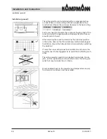
No clearance allowed!
The condensation must be
discharged directly upwards
in a vertical position.
Ventilation
Sizing based on the
condensation
forming
Gradient
Free drain
(DIN EN 1717)
Odour
trap
Waste water network
Ceiling
max. 650 mm


