19
KaCool D
02.02.2017
Design and Function
Overview
6
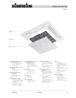
Air outlet
8
Air intake grille
7
Air
fi
lter
1
Punched opening for optional
fresh air connection:
For 20 % fresh air at medium
fan speed (Fig. including
fresh air spigot)
2
Punched opening for external
air
outlet:
Connection option for
on-site air outlets
3
Electrical control box for
Control
PCBs:
KaControl
Infra-red electronic receiver
Terminals only
4
Compact basic housing:
Made of galvanised sheet steel
The outside has a
fl
eece coating
for improved insulation from the
environment
The inside has high-grade
10 mm vapour diffusion-tight
polyethylene foam matting
5
Stylish casing similar to RAL
9003 (signal white):
Dimensions coordinated to
acoustic ceiling grids (with
model 4–6, the casing and the
unit can be centred within four
fi
elds)
6
Air
outlet:
Four manually adjustable
outlet air louvres
made of smooth plastic
Easy to clean
7
Air
fi
lter:
Simple to remove
Easy to clean
8
Air intake grille:
Large free cross-section
to minimise pressure losses
9
Hydraulic
connections:
For CHW, LPHW and drainage
of condensation Valve drip tray
drains
any condensation produced into
the condensation tray
Drip tray is supplied with the unit
10
Condensation pump and
fl
oat switch:
Easily accessible by removal of
the polystyrene condensation
tray Integrated condensation
pump
drains the condensation up to a
max. head of 650 mm
Pump activation by a two-stage
fl
oat switch
The pump is switched on when
the
fi
rst stage is reached and the
second stage activates an
evaluable alarm contact
11
Fans:
3-stage AC fans
In
fi
nitely adjustable EC fans
Vibration-damped mounting
Direct-driven, backward-curved
impeller
Ef
fi
cient and low-noise
Protection class IP 44, insulation
class B
Integrated thermal contacts to
prevent the motor from
overheating
12
Heat
exchanger:
Made of copper pipe with
aluminium
fi
ns
2 / 4 pipe con
fi
guration
Vent and drain valves on the
outside of the unit
Max. operating pressure: 8 bar


