


9
1034790D / January 2001
KTD-400 Controller Keypad Installation and Operation Manual
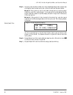
After all the connections are made, the KTD-400 or KTD-300R is ready for operation. Plug
the 12VDC wall transformer into a power outlet. The LCD window will briefly display keypad
setting information, and then it will enter the operating mode.
Powering Up
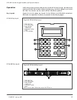
KTS-41 System
Control
Wiring the KTD-300R to control a KTS-41A system involves connecting the RS422 input
cable (if used), the RS422 output cable (if used), the DTMF output cable (to the KTS-41A),
and the 12VDC wall transformer. See Figure 6.
Figure 6: KTD-300R terminal strip connections with KTS-41A control


