


18
1034790D / January 2001
KTD-400 Controller Keypad Installation and Operation Manual
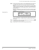
Figure 37: Second Clear Memory Display
ARE YOU SURE?
0=NO 3=YES SEQ=NEXT
Clear Receiver Memory
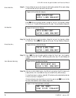
Zoom Direction
Focus Direction
Iris Direction
Step 9)
The next three menus provide choices for defining the polarity of the output voltage
for the motorized lens connected to the receiver.
Press
0
if the lens requires positive voltage for “zoom in” and negative voltage
for “zoom out.” Press
1
if the opposite is the case. The next display will appear.
Step 10)
Press
0
if the lens requires positive voltage for “iris open” and negative voltage
for “iris close.” Press
1
if the opposite is the case. The next display will appear.
Step 11)
Press
0
if the lens requires positive voltage for “focus near,” and negative
voltage for “focus far.” Press
1
if the opposite is the case. The next display will
appear.
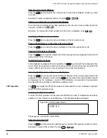
Step 12)
With the CLR RCV MEM option, the KTD-400 will instruct the P/T/Z receiver to
erase all data in its nonvolatile memory and reload factory default values.
To clear the receiver’s memory, press
1
. The display will automatically advance
to the menu shown in Figure 37.
If the clear receiver memory function is not to be used, press
0
to return to the
Receiver Site Selection menu display (Figure 27).
Figure 36: First Clear Memory Display
CLR RCVR MEM? 000
0=NO 1=YES SEQ=NEXT
Figure 33: Zoom Direction Display
ZOOM DIRECTION?
0=POS 1=NEG SEQ=NEXT
Figure 34: Iris Direction Display
IRIS DIRECTION?
0=POS 1=NEG SEQ=NEXT
Figure 35: Focus Direction Display
FOCUS DIRECTION?
0=POS 1=NEG SEQ=NEXT


