background image

1 7

Settings –


Advanced Setting Menu –


Step Parameters

 –


Enter Step Powers

10 5

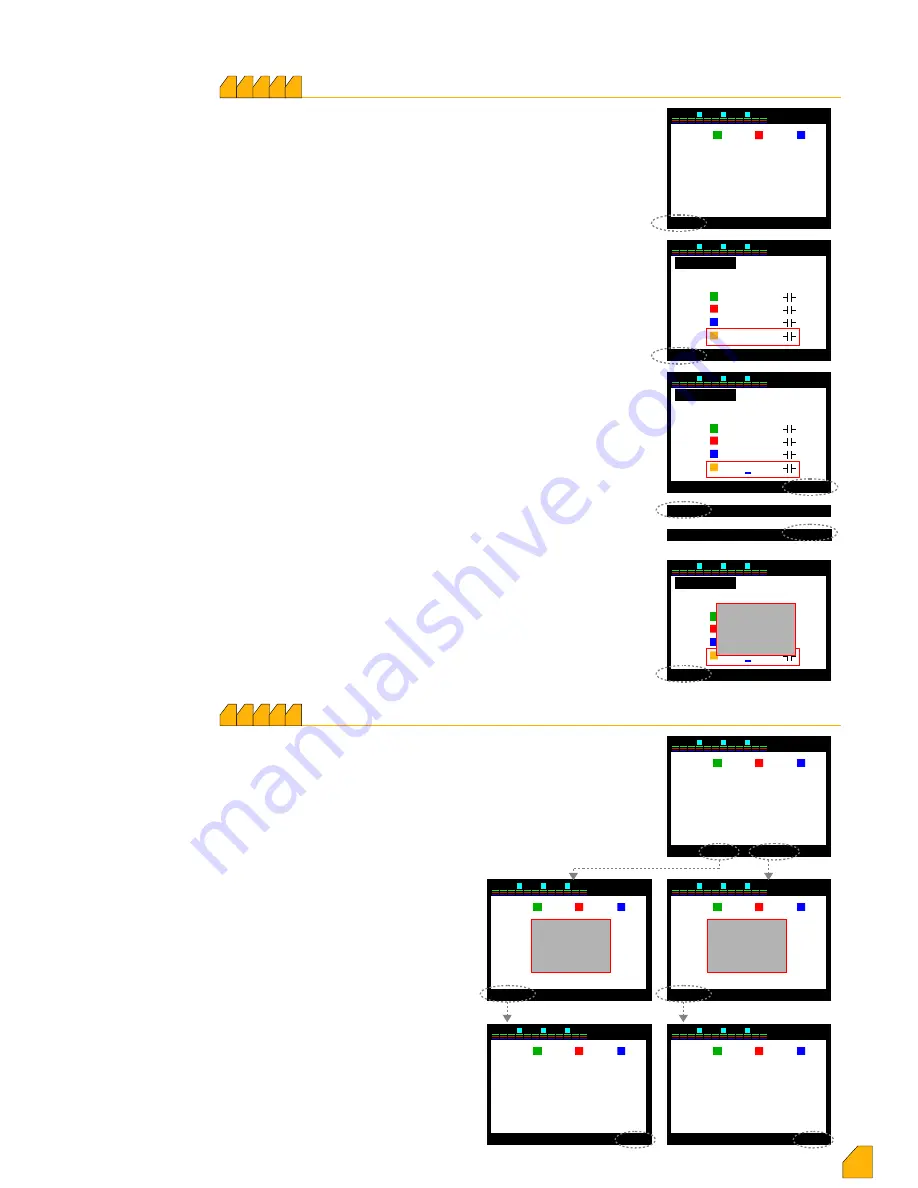
This is the section in which the step powers are entered. The 

device directs the user with subcommand display 

continuously. It is moved on the step of which the power is 

required to be entered by using the up and down keys. In the 

meantime, that line are in red colour. Select key is pressed. 

The selected step number comes to screen. The selection of 

triple-phase or single-phase of capacitor or reactor should be 

made on this screen.

The position of red frame changes when up and down keys 

are used. In case the reactive load on the step is triple-phase, 

the frame is moved on triple-phase and “Select” key is 

pressed. Triple-phase option becomes red in this case. If up or 

down direction key is pressed, the red frame moves to total 

value digit. The “Select” key is pressed and a blue underline 

appears on the last digit inside of the frame. The value is 

setup by using the up and down keys starting from the digit 

where the blue line is. Then, left key is pressed and the blue 

underline moves next to the left digit. All the values are 

entered in the same way by using up and down keys. The 

“Apply” key is pressed to take them into memory. The sub-

command screen changes and “Okay”, then “Exit” key is 

pressed. “Save Changes” will appear on the screen. When 

“Okay” key is pressed, the value is taken into memory.

If the reactive load on the step is single-phase, frame is 

moved onto single-phase and “Select” key is pressed. Single-

phase option becomes red in this case. In case of pressing up 

or down direction key is pressed, the red frame moves on the 

lines of R, S and T-phases including total value. In case of 

which phase the reactive load  on the step is connected to, 

“Select” key is pressed during on that line. Entering the value 

and taking it into memory is the same as described above.

P.S.: Moving the blue underline to the digit on which the sign is 

by using the left key, the sign can be changed by pressing 

upwards key. (+) represents the reactor, (-) represents the 

capacitor.

2 3

5 6

8 9

11 12

7

4

1

10

30

Exit

Kvar

4

Select

R

S

T

K1      ---------      ---------       ---------

K2      ---------      ---------       ---------
K3      ---------      ---------       ---------
K4      ---------      ---------       ---------
K5      ---------      ---------       ---------

Step powers are adjusted manually...

2 3

5 6

8 9

11 12

7

4

1

10

14

30

Exit

3-phase

Select

R

S

T

1.Step

1-phase

Σ

0.000 KVAr
0.000 KVAr
0.000 KVAr
0.000 KVAr

2 3

5 6

8 9

11 12

7

4

1

10

30

3-phase

R

S

T

1.Step

1-phase

Σ

0.000 KVAr
0.000 KVAr
0.000 KVAr
0.000 KVAr

Apply

▲ +

▼ -

Cancel

Okay

Exit

Exit

Select

2 3

5 6

8 9

11 12

7

4

1

10

30

3-phase

R

S

T

1.Step

1-phase

Σ

0.000 KVAr
0.000 KVAr
0.000 KVAr
0.000 KVAr

Cancel

Okay

Exit

Save

changes

1 7

Settings –


Advanced Setting Menu

 –


Step Parameters

 –


Delete Step Powers

10 5

2 3

5 6

8 9

11 12

7

4

1

10

30

Exit

Kvar

5

Delete

R

S

T

K1      -0,500      -0,500       -0,500
K2      -1,000      -1,000       -1,000
K3      -1,500      -1,500       -1,500

K4      -2,500      -2,500       -2,500

K5      -3,330      -3,330       -3,330

2 3

5 6

8 9

11 12

7

4

1

10

30

Kvar

R

S

T

K1      -0,500      -0,500       -0,500
K2      -1,000      -1,000       -1,000
K3      -1,500      -1,500       -1,500

K4      -2,500      -2,500       -2,500

K5      -3,330      -3,330       -3,330

2 3

5 6

8 9

11 12

7

4

1

10

30

Kvar

R

S

T

K1      -0,500      -0,500       -0,500
K2      -1,000      -1,000       -1,000
K3      -1,500      -1,500       -1,500

K4      -2,500      -2,500       -2,500

K5      -3,330      -3,330       -3,330

2 3

5 6

8 9

11 12

7

4

1

10

30

Kvar

R

S

T

K1      -0,500      -0,500       -0,500
K2      -1,000      -1,000       -1,000
K3      -1,500      -1,500       -1,500

K4      ---------     ---------      ---------

K5      -3,330      -3,330       -3,330

2 3

5 6

8 9

11 12

7

4

1

10

30

Kvar

R

S

T

K1      ---------     ---------      ---------

K2


     ---------     ---------      ---------

K3


     ---------     ---------      ---------

K4


     ---------     ---------      ---------

K5


     ---------     ---------      ---------

Cancel

Okay

Exit

Cancel

Okay

Exit

Step

  Delete ?

Step

  Delete ?

Exit

Delete

Delete All

Exit

Delete

Delete All

This is the section in which the step parameters are deleted 

one by one, or all. In case the reactive load is changed in any 

step, the power of that step must be deleted to let the device 

internalize the the power of new step. The device fowards the 

user continuously by sub-command screen. Moving onto the 

step of which power required to be deleted, the up or down 

key is pressed. The line is in red colour in the meantime. In 

case of deleting only that step, “Delete” key is pressed; in case 

of deleting all steps (if a device used in somewhere

else is connected to a new plant),

“Delete All” key is pressed.   

If “Delete” key is pressed, “Step Delete?” 

warning appears on the screen. When

 “Okay” key is pressed, the power of

that step would be deleted. The device

will automatically try to internalize the

power of that step again. You can exit

the menu by “Exit” key. In case “Delete

All?” key is pressed, “Steps Delete?”

warning appears on the screen.  When

“Okay” key is pressed, the power of all

steps would be deleted.  The device

will automatically try to internalize the

power of that step again. You can exit

the menu by “Exit” key.

17

Delete All

Summary of Contents for VARkombi-12-PC-TFT-OG

Page 1: ...dislik Elektronik Tic ve San Ltd ti Reactive Power Control Relay Industrial Facilities Markets Oil Stations Schools Workshops Hotels 12 Step VARkombi 12 PC TFT OG Connection type selective VARkombi 12...

Page 2: ...7 8 Current Transformer Primary Value 1 7 9 Number of Steps 1 7 10 Advanced Set up Menu 1 7 10 1 T on Transition Delay Time 1 7 10 2 T off Transition Delay Time 1 7 10 3 Current Flow Direction Detecti...

Page 3: ...ver Temperature 1 7 10 6 2 4 Voltage THD Setting 1 7 10 6 2 5 Voltage HD Setting 1 7 10 6 2 6 Current THD Setting 1 7 10 6 2 7 Current HD Setting 1 7 10 6 3 Fan Settings 1 7 10 6 3 1 Fan Temperature V...

Page 4: ...the device for different purposes other than compensation system 6 Fix the device tightly on the control panel with the apparatus given on the device without hanging around 7 Do not interfere to the...

Page 5: ...king compensation for the generator according to the second Cos 2 set up Displaying many guiding screens operating system is used in the micro processor Computer communicated RS485 MODBUS RTU Password...

Page 6: ...g to the specified current value The outputs of the steps are not needed to be made in any order However the first 6 steps can consist of triple phase capacitor groups It is recomended to connect sing...

Page 7: ...er the other according to the priority Meanwhile the phase in which the alarm is given displayed on the screen Arrow keys can move between the alarms In case Select key is pressed during on any alarm...

Page 8: ...e checked again in case any power of the steps and their connections are not intenalized for a long time 5 Step Learning of step powers For more info When all the steps are internalized the main scree...

Page 9: ...umptions Instant consumption values of each phase and their scaled representation the normal under and over compensation of the phases their inductive capacitive characterized loads and whether the sy...

Page 10: ...rol Otherwise the device remains in manual control continuously 1 2 3 4 5 6 7 8 9 11 10 12 30 Menu Cos PF Steps 0 R S T 0 ind cap ind cap ind cap S T Q 1 763K P 21 44K PF 0 991 0 155K 14 66K 0 999 1 4...

Page 11: ...tep with red frame among the step boxes is displayed on the left side of the screen while moving with directon keys The information regarding the runtime of all steps number of switching phase or phas...

Page 12: ...ave Changes appears on the screen the data are kept in the memory by pressing Okay key Settings This is the section in which you can find all set up regarding the device Password is entered After comm...

Page 13: ...r DYN 5 NOTE The current transformer ratio must be entered in the section from the menu 1 7 8 select exit 1 7 Measurement types MV LV ratio Transformer Type 2 3 5 6 8 9 11 12 7 4 1 10 30 1 1 Enter MV...

Page 14: ...1 10 30 Connection MEDIUM VOLTAGE LOW VOLTAGE Voltage become isolated The value of the voltage transformer must be entered NOTE The current transformer ratio must be entered in the section from the m...

Page 15: ...or the deadline This causes delays in the compensation VARkombi 12 PC TFT OG It collects the energies ind cap active consumed Step activating and de activating periods are decreased or increased autom...

Page 16: ...lows down by means of dynamic control of switch off time and continously do not make fast moves unnecessarily P S 1 Switch off time counts only for capacitor activated newly If necessary and a close s...

Page 17: ...ge will appear on the screen When Okay key is pressed the value is taken into memory Enter cap penalty limit 2 3 5 6 8 9 11 12 7 4 1 10 30 Apply 10 Enter cap penalty limit 2 3 5 6 8 9 11 12 7 4 1 10 3...

Page 18: ...s are entered in the same way by using the up and down keys Press Apply key inorder to take T off switching time into memory Save changes message will appear on the screen When Okay key is pressed the...

Page 19: ...ation in some plants especially the plants in which the loads are changing very quickly The required status for function is selected by using the up and down keys Press Apply key inorder to take this...

Page 20: ...2 3 5 6 8 9 11 12 7 4 1 10 14 30 Exit 3 phase Select R S T 1 Step 1 phase 0 000 KVAr 0 000 KVAr 0 000 KVAr 0 000 KVAr 2 3 5 6 8 9 11 12 7 4 1 10 30 3 phase R S T 1 Step 1 phase 0 000 KVAr 0 000 KVAr 0...

Page 21: ...00 K Step Change 2 3 4 5 6 8 9 10 11 12 16 17 14 15 1 7 13 2 3 5 6 8 9 11 12 7 4 1 10 30 Exit Load New value Old value Old value R S T 0 000 K 0 000 K 0 000 K 0 000 K Step Change 2 3 4 5 6 8 9 10 11 1...

Page 22: ...under compensation in any phase during the activation of alert device warns the user In this case Review the capacitor power distribution in the steps especially in the phase where the alert is given...

Page 23: ...s may blowed out The fuses in the power line of capacitors may blowed out Removing the failure steps internalized zero should be internalized again 1 7 10 6 1 General Alarms Over Temperature enable 2...

Page 24: ...digit All values are entered in the same way by using up and downkeys Select key is pressed to take them into the memory Save changes message will appear on the screen Pressing Okay key the value is...

Page 25: ...essing Okay key the value is taken into the memory 5 005 Voltage HD Alarm Setting HDV Save Changes In case harmonic protection is activated in the step protection function Chapter 1710643 all steps ar...

Page 26: ...0 30 Apply disable Fan Output 1 7 10 6 4 Setting Advanced Setting Menu Alarm Protection Step Protection Function De activation of the capacitors is recommended to protect them against temperature volt...

Page 27: ...30 Apply Enable User Password Status 2 3 5 6 8 9 11 12 7 4 1 10 30 Exit Password active passive Password change 1 7 9 7 2 PASSWORD Enter old password 0 2 3 5 6 8 9 11 12 7 4 1 10 30 Exit Password acti...

Page 28: ...ssword should be entered to write data This is the section in which the password is entered The value is setup to the required value by using the up and down key starting from the digit where the blue...

Page 29: ...ing Okay key the value is taken into the memory Device No 001 255 The value is setup to the required value by using the up and down key starting from the digit where the blue line is Then left key is...

Page 30: ...ting Values THD Current 30 Alarm Setting Values HD Current 30 Fan Settings Fan Temperature Value 50 C Fan Settings Fan Output disable Level Protection Function Temperature Protection disable Level Pro...

Page 31: ...Class IP 20 Terminal Protection Class IP 00 Environment Temperature 5 C 50 C Humudity 15 95 without condensation Device Standart EN 55011 2007 A2 2007 EN 61326 2006 EN 61000 3 2 2006 EN 61000 3 3 1995...

Page 32: ...A CALCULATION CHART ACCORDING TO CAPACITOR CONNECTION FORMAT Capacitor Powers 3 Phase Connection Phase Neutral Connection Phase Neutral bridged Connection Phase Phase Connection Phase Phase bridged Co...

Reviews: