


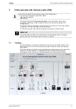
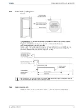


Online operation with firmware option cDML
46
k4evo707en-2012-07
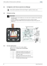
5.4.3 RS-485
interface
The Compact Reader communicates with the access hub via the RS-485 interface.
For information on the RS-485 cable, see Chapter 3.2.1/Page 23
and on the cabling/bus termination, Chapter 3.5.1/Page 25.
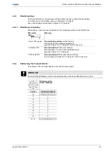
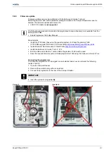
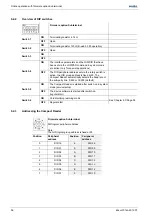
5.4.3.1 RS-485 bus termination
DIP switches 1 and 2 are used to determine the terminating resistor on the RS-485 bus.
DIP switch
Meaning
1 and 2 OFF (open)
No terminating resistor
(within the bus)
for devices in a bus cabling arrangement;
see also Chapter 3.5.1.1/Page 25 -
with 1/2 bus lines
1 ON and 2 OFF
Bus termination 4.7 k
Ω
;
(star cabling)
Bus termination 4.7 k
Ω
on each individual device;
see also Chapter 3.5.1.2/Page 26
1 OFF and 2 ON
Bus termination 120
Ω
;
(start and end of bus)
for bus cabling; Chapter 3.5.1.1/Page 25 -
with 1/2 bus lines
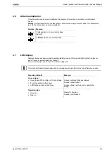
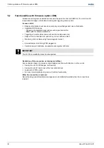
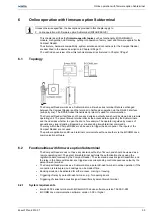
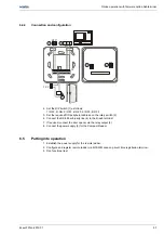
5.4.4
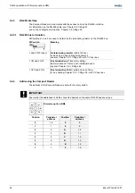
Addressing the Compact Reader
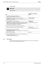
The address of the Compact Reader is set with the rotary switch:
IMPORTANT
Ensure that the addresses of all the connected devices on the same RS-485 bus are unique
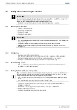
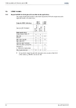
Firmware option cDML
Position
Peripheral
address
Position
Peripheral
address
0
16
8
8
1
1
9
9
2
2
A
10
3
3
B
11
4
4
C
12
5
5
D
13
6
6
E
14
7
7
F
15