background image

5

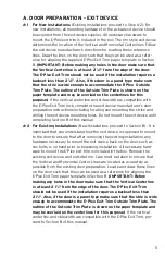
A. DOOR PREPARATION - EXIT DEVICE

A-1

For New Installations

(Existing Installations proceed to Step A-2): For

new installations, all mounting hardware for the actual exit device should

be acquired from the exit device supplier. All necessary hardware to

mount the E-Plex exit trim is included in the box. The rim style exit device

determines the location of the Vertical and Horizontal Centerlines. Follow

the exit device manufacturer’s directions for locating these reference

lines. Draw the lines on the door such that they can be used as a refer-

ence for aligning the supplied E-Plex Exit Trim paper template in Section

B.

(IMPORTANT: Before making any holes in the door make sure that

the Vertical Centerline is at least 2

1

4

" from the edge of the door.

The E-Plex Exit Trim should not be used if the installation requires a

backset less than 2

1

4

". Also, if the door is a panel type make sure

that the stile is wide enough to accommodate the E-Plex Outside

Trim Plate. The outline of the Outside Trim Plate is shown on the

paper template and may be overlaid on the centerlines for this

purpose.)

If the vertical centerline and stile width are compatible with

the E-Plex Exit Trim lock, complete the exit device manufacturer’s door

preparation instructions including locating and mounting the strike and

drilling the exit device mounting holes. Do not mount the exit device until

completing Section B of this manual.

A-2

For Existing Installations

(New Installations proceed to Section B): It is

important that you understand how the exit device is supposed to mount

to the door to ensure that after removing the existing installation, any

hardware necessary to mount the exit device back on the door, such as

sex bolts, is on hand prior to beginning installation. All necessary hard-

ware to mount the E-Plex exit trim is included in the box. Remove the

existing exit device and outside trim. Care must be taken to ensure that

the Vertical and Horizontal Center Lines are located as accurately as

possible from the existing door preparation. Locate and draw these lines

on the door such that they can be used as a reference for aligning the

E-Plex Exit Trim paper template in Section B.

(IMPORTANT: Before

making any holes in the door make sure that the Vertical Centerline

is at least 2

1

4

" from the edge of the door. The E-Plex Exit Trim

should not be used if the installation requires a backset less than

2

1

4

". Also, if the door is a panel type make sure that the stile is wide

enough to accommodate the E-Plex Exit Trim Outside Trim Plate. The

outline of the Outside Trim Plate is shown on the paper template and

may be overlaid on the centerlines for this purpose.)

If the vertical

centerline and stile width are compatible with the E-Plex Exit Trim, pro-

ceed to Section B of this manual.

Summary of Contents for E-Plex 5X10

Page 1: ...5X10 EXIT TRIM MODELS INSTALLATION INSTRUCTIONS...

Page 2: ...Models 9 J Installing E5x00 Exit Trim 11 K Installing The Battery Pack and Cover Changing Batteries 12 L Testing the Operation of the Lock 13 M Reset Function 14 Warning The Master Code of this lock...

Page 3: ...from 1 3 4 to 21 8 A door thick ness of up to 21 4 inches can be accommodated through the addi tion of a spacer ring The E Plex Exit Trim accommodates through bolt mounting as used in most fire rated...

Page 4: ...s handing is properly set only a downward rotation of lever will actuate latch 2 Key Override Use The key override differs in that rotating the key does not actuate the latch To use the key override t...

Page 5: ...strike and drilling the exit device mounting holes Do not mount the exit device until completing Section B of this manual A 2 For Existing Installations New Installations proceed to Section B It is im...

Page 6: ...dy have a through bore at the intersection of the Vertical and Horizontal Centerlines if the existing hole is smaller than 2 1 8 54 mm in diameter it will need to be enlarged Extra care should be used...

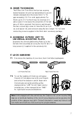
Page 7: ...tside Unit Assembly b using the four 10 24 x 3 4 long screws c supplied in the accessory kit F LOCK HANDING F 1 Determine the handing of your door from the following diagram F 2 To set the handing of...

Page 8: ...substituted with a foreign part If the lock is used with a wall bumper the warranty is null and void If a doorstop is required we recommend the use of a floor secured stop The environment and conditi...

Page 9: ...CONTROL 2941 INDIANA AVENUE WINSTON SALEM NC 27199 3770 NO POSTAGE NECESSARY IF MAILED IN THE UNITED STATES BUSINESS REPLY MAIL FIRST CLASS MAIL PERMIT NO 1563 POSTAGE WILL BE PAID BY ADDRESSEE WINST...

Page 10: ...Exercise Room This lock is New Installation Replacing a conventional keyed lock Replacing a Kaba Mechanical Pushbutton Lock Replacing a Kaba Electronic Access Control Replacing a Keyless Lock other t...

Page 11: ...Notes...

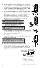
Page 12: ...our KIL cylinder You must use a Kaba tailpiece The K 2 tailpiece is preassembled with the Kaba 1599 G 3 Assemble the required tailpiece d supplied with your KIL cylinder All tailpieces must be install...

Page 13: ...de unit assembly follow the steps below H 4 Insert one of the supplied keys a into the outside lever b and rotate it counterclockwise 45 degrees Insert release tool d into the small hole e under lever...

Page 14: ...e Note You may want to use needle nose pliers for some tailpieces Insert the release tool d into the small hole f under lever as shown Gently push lever catch up until it clicks Remove tool then remo...

Page 15: ...ove tool then remove outside lever a J INSTALLING E5x00 EXIT TRIM Note Prior to mounting the lock ensure the handing is set correctly as the tailpiece may have shifted during handling see section F Wa...

Page 16: ...htening the LectroBolt to secure the lock to the door Note Do not shut door until installing batteries and testing operation as outlined in the following two sections K INSTALLING THE BATTERY PACK AND...

Page 17: ...ended position L 2 Enter the factory set combination 1 2 3 4 5 6 7 8 You see a green light and hear a tone as you push each button When the lock opens you will briefly hear the sound of an electric mo...

Page 18: ...und of lock resetting and a high pitch tone 6 Green light flashes Lock is reset to factory mode Note For security reasons all existing audit events are not deleted The lock is now set to the factory c...

Page 19: ...15 Notes...
Page 20: ...Kaba Access Control 2941 Indiana Avenue Winston Salem NC 27105 USA Tel 800 849 8324 336 725 1331 Fax 800 346 9640 336 725 3269 www kabaaccess com www e plexlock com PKG3055 0608...

Reviews: