12
J-4
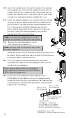
Insert the LectroBolt through the red battery mounting plate hole marked
with the lightning bolt symbol. For now, only partially tighten the
LectroBolt enough to hold the Outside Unit assembly and the battery
mounting plate in place on the door.
J-5
Insert the two Mounting Bushings (f) into the lower two holes on the
inside of the door.
J-6
Select the proper length Mounting Screws (g) for the door thickness: use
the 1
3
⁄
4
" screw for door thickness range from 2
1
⁄
4
" to 2", for door thick-
ness range of 2
1
⁄
8
" to 2
1
⁄
4
" use the 2
1
⁄
4
" long screws included in the thick
door accessory pack. Insert two of the Mounting Screws into two lower
mounting holes and tighten securely.
J-7
Place the supplied lock washer (h) on the remaining mounting screw, and
insert in to the uppermost mounting hole and fasten securely to the sex bolt.
J-8 Important
: Once the regular mounting screws have been tightened finish
tightening the LectroBolt
™
to secure the lock to the door.
Note:
Do not shut door until installing batteries and testing operation as
outlined in the following two sections.
K. INSTALLING THE BATTERY PACK AND
COVER / CHANGING BATTERIES
K-1
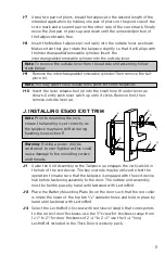
To Install the Battery Pack (a) and
cover (b), snap the cable connector (c)
onto the top of the battery pack. Then
place the battery pack into the cover
with the terminals at the top. Put the
two security screws (d) into the cover
and fasten to the battery mounting
plate with the security screw wrench
(e).
Important
: Do not shut door until
testing operations as directed in sec-
tion L.
Caution
: Over-tightening these screws could strip the threads in the housing or
crack the cover.
Warning:
If the lock’s date and time have been set, and then power is
removed from the lock for more than 2 minutes, the lock’s current date
and time will need to be set again. Please refer to Lock Operations Manual
for instructions on setting the date and time.
K-2
To change batteries remove the two screws (d) from the battery cover (d)
using the security screw wrench (e) provided with your lock.
c
e
a
b
d
Summary of Contents for E-Plex 5X10
Page 1: ...5X10 EXIT TRIM MODELS INSTALLATION INSTRUCTIONS...
Page 11: ...Notes...
Page 19: ...15 Notes...

