4-12
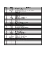
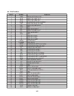
PIN NO.
PIN NAME
DESCRIPTION
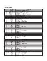
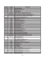
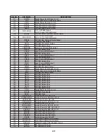
111
IOVDD
Digital Power for I/O Pads (3.3 V)
112
VSS
Digital Ground for Core and IO Pads
113
VDD
Digital Power for Core (1.2 V)
114
STEP1
Sled Step Motor PDM Output
115
STEP2
Sled Step Motor PDM Output
116
RWE#
SDRAM Write Enable Output
117
TILT/ FOO2
TILT: Tilt PDM Output
FOO2: Focus Tilt PDM Output
118
RCAS#
SDRAM Column Address Strobe Output
119
FOO/ FOO1
FOO: Focus PDM Output
FOO1: Focus Tilt PDM Output
120
RRAS#
SDRAM Row Address Strobe Output
121
TRO
Tracking PDM Output
122
RCS#
SDRAM Chip Select Output
123
RAD13
SDRAM Address Bus
124
VREFPDM
Reference Voltage PDM Output
125
RAD10
SDRAM Address Bus
126
LDEL2
Laser Control PDM Output
127
RAD0
SDRAM Address Bus
128
LDEL1
Laser Control PDM Output
129
RAD1
SDRAM Address Bus
130
LDEL0
Laser Control PDM Output
131
RAD2
SDRAM Address Bus
132
LTHR
Laser Control PDM Output
133
RAD12
SDRAM Address Bus
134
DQM0
SDRAM Byte Mask Output
135
IOVDD
Digital Power for I/O Pads (3.3 V)
136
VSS
Digital Ground for Core and IO Pads
137
DQM1
SDRAM Byte Mask Output
138
RAD3
SDRAM Address Bus
139
RAD4
SDRAM Address Bus
140
RAD5
SDRAM Address Bus
141
RAD6
SDRAM Address Bus
142
RAD7
SDRAM Address Bus
143
RAD8
SDRAM Address Bus
144
RAD9
SDRAM Address Bus
145
RAD11
SDRAM Address Bus
146
VDD
Digital Power for Core (1.2 V)
147
RCLKE
SDRAM Clock Enable
148
RCLK SDRAM
Clock
149
VSSADCPLL
Analog Ground for ADC PLL
150
VDD3ADCPLL
Analog Power for ADC PLL (3.3 V)
151
VSSHFLDR
Analog Ground for HF LDR
152
VDD3HFLDR
Analog Power for HF LDR (3.3 V)
153
VSSHFADC
Analog Ground for HF ADC
154
VDD3HFADC
Analog Power for HF ADC (3.3 V)
155
VDD3DPD
Analog Power for AFE DPD (3.3 V)
156
VDD3RF
Analog Power for AFE RF (3.3 V)
157
EQDON
RF Output and Testing Port
158
EQDOP
RF Output and Testing Port
159
VSSDPD
Analog Ground for AFE DPD
160
VSSRF
Analog Ground for AFE RF
161
MUXOUT2
Un-Buffered Analog Test Output 2
162
MUXOUT1
Un-Buffered Analog Test Output 1
170
GPADC1
General Purpose ADC Channel 1 Input
171
BDRFP
BD Summed RF Input
172
BDRFN
BD Summed RF Input
Summary of Contents for XV-BP10J
Page 64: ...3 65 3 66 3 KEY P C BOARD TOP VIEW 4 TIMER P C BOARD TOP VIEW BOTTOM VIEW BOTTOM VIEW ...
Page 65: ...3 67 3 68 MEMO MEMO ...
Page 74: ...4 9 1 2 Block Diagram BCM7620 ...
Page 79: ...4 14 2 LIC200 R2A30209SP W02Z SPINDLE MOTOR AND 6CH ACTUATOR DRIVER 2 1 Block Diagram ...
Page 83: ...4 18 MEMO ...
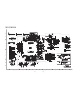
Page 84: ...4 20 4 19 CIRCUIT DIAGRAM A 1 2 3 4 5 6 7 8 9 10 11 12 B C D E F G H I J K L M N O P Q R S T ...


