background image

78

Connecting to a PC – Connecting to a Web Browser and Setting Up – (continued)

1.

Click the 

 button

• Right-click on “My Network Places” and select “Properties”.

2.

Select the network for which the PC used for Web
browser operation is connected

• Right-click and select “Properties”.

• Proceed to page 80 step 

3.

• “METHOD”

: [STATIC] (DHCP not used)

• “IP ADDRESS”

: 192.168.0.10

• “SUBNET MASK”

: 255.255.255.0

• “DEFAULT GATEWAY”

: 192.168.0.254

• “Workgroup”

: [WORKGROUP]

Notes

• Install accordingly if [Client for Microsoft

Networks] and [Internet Protocol (TCP/IP)]
are not displayed.
Refer to Windows Help Menu for the in-
stallation procedure.

What is TCP/IP?

 Page 110

What is DHCP?

 Page 110

What is Workgroup?

 Page 110

When Using Windows XP

Setting Up a PC Network (Windows XP)

1

 Check the ticked items.

• Method

: STATIC

• “IP address”

: 192.168.0.12

• “Subnet mask”

: 255.255.255.0

• “Default gateway”

: 192.168.0.254

• “Workgroup”

: [WORKGROUP]

• Method

: STATIC

• “IP address”

: 192.168.0.11

• “Subnet mask”

: 255.255.255.0

• “Default gateway”

: 192.168.0.254

• “Workgroup”

: [WORKGROUP]

• Method

: STATIC

• “IP address”

: 192.168.0.13

• “Subnet mask”

: 255.255.255.0

• “Default gateway”

: 192.168.0.254

• “Workgroup”

: [WORKGROUP]

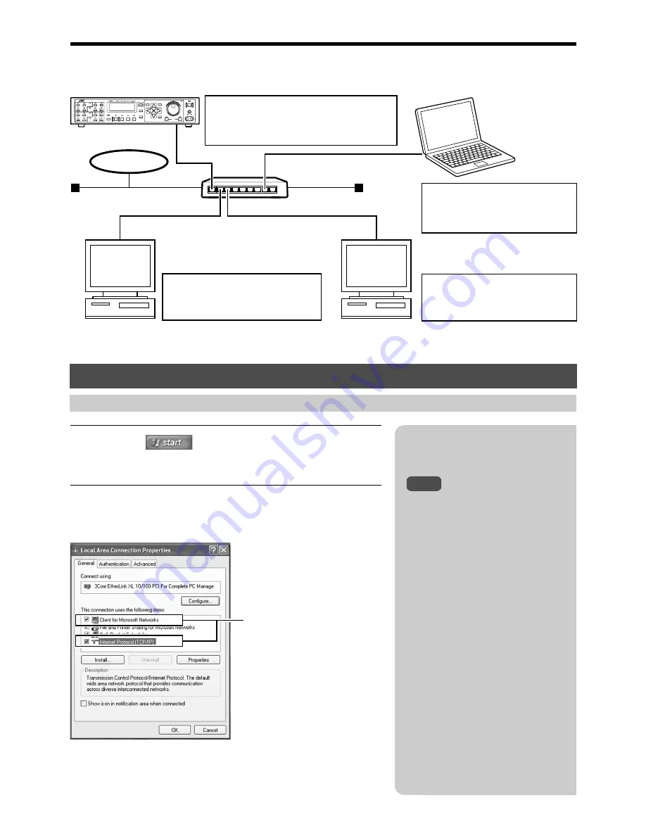
The following illustrates how to set up a small LAN using VR-716’s factory settings.

Example

PC for Web Browser
Operation

Other Network PC 1

Other Network PC 2

Hub

LAN

ALARM

SENSOR

SEQUENCE

MULTI

REC

STOP

PLAY

STILL

DISPLAY

CANCEL

SEARCH

MENU

REV

SKIP

FWD

HDD

OPERATE

LOCK

VIDEO

AUDIO

OUT

EXECUTE

ALARM

SENSOR

ALARM

SENSOR

ALARM

SENSOR

11

1

9

10

3

4

1

2

7

8

5

6

13

14

15

16

TIMER

Summary of Contents for VR-716E

Page 1: ...pdf under the VR 716E_Manual folder in the provided CD ROM For re ference method please see page 3 DEUTSCH Die Bedienungsanleitung ist unter dem Namen VR 716E_de pdf im Ordner VR 716E_Manual auf der beiliegenden CD ROM gespei chert Hinweise zur Benutzung finden Sie auf Seite 3 FRANÇAIS Le manuel de l utilisateur est archivé sous le nom de VR 716E_ fr pdf dans le dossier intitulé VR 716E_Manual du ...

Page 2: ...late and the safety caution are on the rear of the unit The OPERATE button does not completely shut off mains power from the unit but switches operating current on and off WARNING It should be noted that it may be unlawful to re record pre recorded tapes records or discs without the consent of the owner of copyright in the sound or video recording broadcast or cable programme and in any literary d...

Page 3: ...energy be sure to turn off the system when not in use WARNING This is a Class A product In a domestic environment this product may cause radio interference in which case the user may be required to take adequate measures WARNING For PLUGGABLE EQUIPMENT the socket outlet shall be installed near the equipment and shall be easily accessible How to read the Instruction manual pdf file SAFETY PRECAUTIO...

Page 4: ... of Recording Via External Alarm Sensor Signals 66 Using the Motion Detect Feature 68 Motion detect check mode and setting guidance 70 Continuing with Recording Upon Recovery from Power Failure 71 Setting a Title for Each Camera Channel Screen 72 Table of Content Connecting to a PC What is a Web Browser You can do the followings 73 Cautions for Proper Use of the Web Browser 74 Setup Flow 75 Connec...

Page 5: ...el asynchronous camera inputs Simultaneous recording playback of images in 16 asynchronous cameras Network compatible Recorded images can be viewed on LAN con nected computers Titles and timer programs can also be set using computers Motion Detect Automatically detects image motion within the specified area and starts alarm recording Digital Water Mark Embeds data in images to protect data integri...

Page 6: ...pplied with this equipment on other devices 䡵 Please note that we will not provide compensation for any failure during recording or playback due to defects in this equipment or the hard disk drive 䡵 TV broadcast or other video audio recordings are for personal use only Unauthorized use of these materials is strictly prohibited 䡵 Please note that recorded images will be erased when replacing hard d...

Page 7: ...C Button Press this button when in the Stop or Play mode to start recording Recording mode can be specified on the menu screen Page 36 Recording Camera Images STOP Button Press this button to stop playing Press this button when in the Simultaneous Record Play mode to stop playing and switch to the normal recording mode Names and Functions Front Note Note PLAY Button Press this button to start play...

Page 8: ...y will start to blink The ON OFF of BUZZER depends on the WARNING set ting in the BUZZER Menu Page 24 BUZZER Menu Page 46 Record Programming Using the ProgramTimer ALARM SENSOR LED Blocks every 4 entries that are in the Alarm Recording Standby or Sensor Recording Standby modes will light up in green SEQUENCE MULTI Split Screen Display Switch ing Button and LED Press this button to change the displ...

Page 9: ...ction to the Intranet and other networks using a LAN cable Page 76 Connecting Using a LAN Cable AUDIO OUT 1 2 Terminals 1 and 2 RCA Outputs the audio input when in the Recording or Stop mode Outputs recorded audio when in the Play mode However there will be no audio output in the following circumstances When playing back recorded images for which the frame rate is set as 1 6 IPS 1 image per 6 seco...

Page 10: ...value Page 61 Series Recording Using 2 or More VR 716 Re corders 4 SERIES REC IN Terminal Series recording will start upon the input of SERIES REC OUT signals This is the terminal that accepts the series recording signals of other VR 716s when multiple sets of VR 716 are used Page 61 Series Recording Using 2 or More VR 716 Re corders Getting Started continued Names and Functions Signal In Out Term...

Page 11: ...ss Ensure that the impedance at the output is 10 k or less High Voltage 5 V Low Voltage 0 V Grounded Input 44 k High Voltage 5 V Low Voltage 0 V Open Collector High Voltage 5 V Low Voltage 0 V Grounded Input 44 k High Voltage 12 V Low Voltage 0 V High Output 4 7 k High Voltage 5 V 12 V High Input 44 k High Voltage 5 V Low Voltage 0 V Grounded Input 44 k High Voltage 5 V Low Voltage 0 V LOW Output ...

Page 12: ...ng the Alarm Sensor Recording mode Light will start to blink upon completion of alarm sensor re cording 7 LOCK Lock Indicator Lights up when the operation lock is enabled 8 Alarm Recording Indicator Lights up when in the Alarm Recording Standby mode Page 66 Activation of RecordingVia External Alarm Sen sor Signals 9 Sensor Recording Indicator Lights up when in the Sensor Recording Standby mode Pag...

Page 13: ...cording conditions of each BLOCK when in the normal record ing Timer Recording or Alarm Recording mode When in the Stop or Timer Standby mode however conditions for each BLOCK during normal recording are displayed In addition recording conditions of the images currently being played will be shown with priority when in the Play mode Page 105 Problems Related to Error Code and Onscreen Display DISPL...

Page 14: ...d with the BNC connector the built in 75 terminal will be left OPEN In this case connect a 75 terminal to the last device For connection of devices other than VR 716 please refer to the respective instruction manuals for details Please refer to Page 73 Connecting to a PC for connection with computers Caution Notes Connection with up to 16 cameras is possible with VR 716 s switcher Perform recordin...

Page 15: ... disabled during sys tem checks Do so after the SYSTEM CHECKING PLEASE WAIT display disappears Turn ON the power of this equipment only after connections with all peripheral devices are completed Do not unplug the power cord when start ing up this equipment This may cause the equipment to malfunction Caution Press the OPERATE button once when in the OFF state to turn ON the power Unplug the power ...

Page 16: ... if the hard disk contains recorded data Playback Skip Jump or Direct Jump by Date Time may not properly function if there is overlap in the recording dates Date Time setting is disabled when in the Recording mode Refer to the notes related to Summer Time Page 116 Caution 1 Press the MENU button This displays the MAIN MENU OP ERATION MENU screen on the moni tor 2 Select the CLOCK SET item using an...

Page 17: ... the moni tor 6 Select the CLOCK SET item using Move the cursor to select 7 Press to move the cursor to CLOCK SET and turn the jog dial to adjust D Day Turn the jog dial to increase decrease the value 8 Press and turn the jog dial to adjust M Month Repeat Step 8 to adjust the Y Year H Hour and M Minute values ac cordingly 9 Press to move the cursor to RETURN Press to return to the MAIN MENU OPERAT...

Page 18: ...r and minute values 7 Press the DISPLAY button This sets and starts the clock Pay attention when changing dates if the hard disk contains recorded data Playback Skip Jump or Direct Jump by Date Time may not properly function if there is overlap in the recording dates The TIME ZONE item cannot be altered on the front display Refer to the notes related to Summer Time Page 116 Caution Date Time setti...

Page 19: ...ay Po sition Adjustment mode Background color of the Date Time Display turns blue 2 Move using the buttons The position can be moved diagonally by pressing buttons simultaneously Move the Date Time Display to any posi tion However it cannot be shifted to the Warn ing Display Area 3 Press the EXECUTE button The Title Display turns blue and is now in the Onscreen Display Position Adjustment mode 4 M...

Page 20: ...ODE 3 QUAD PICTURE MODE BLOCK 1 BLOCK 2 BLOCK 3 BLOCK 4 4 ALARM SENSOR SWITCH 5 SPLIT SCREEN BORDER COLOR MONITOR DISPLAY 1 4 1SEC 1SEC 1SEC 1SEC OFF BORDER 3 1 RECOVERY REC PRIOR STATE OFF OFF OFF ALL OFF ENGLISH 2 REPEAT REC 3 LANGUAGE SELECTION 4 WATER MARK 5 OPERATION LOCK EXT REC 1 EXT REC MODE 2 SERIES REC OPERATION EXT REC OPERATION 1 DATE TIME 2 PLAYBACK MODE 3 TITLE 4 ALARM SENSOR COUNT 5...

Page 21: ...SCENE AREA SETTING MANUAL 4 CAMERA 3 SCENE AREA SETTING MANUAL 5 CAMERA 4 SCENE AREA SETTING MANUAL 1 NETWORK 1 HOST NAME 2 METHOD 3 IP ADDRESS 4 NET MASK 5 DEFAULT GATEWAY 6 NAME SERVER MAC ADDRESS RETURN CANCEL DELETE 2 DATE TIMER 3 AFTER RELEASE PROGRAM TIMER CONTINUE 1 WEEKLY TIMER WEEKLY TIMER CAM1 4 CAM5 8 CAM9 12 CAM13 16 EXEC START END RETURN CANCEL CANCEL SUN MON TUE WED THU FRI SAT DAY S...

Page 22: ...16 preset values Factory settings during purchase according to its use Connect the monitor for which the menu screen is to be displayed to the VIDEO OUT terminal Page 33 Notes AY EL SEARCH MENU REV SKIP FWD HDD OPERATE LOCK VIDEO AUDIO OUT EXECUTE R 1 6 5 2 3 4 MENU CLOCK SET ONSCREEN MODE FDP BUZZER REC MODE CAMERA TITLE OPERATION EXT REC MONITOR DISPLAY ALARM SENSOR MODE PROGRAM TIMER NETWORK DI...

Page 23: ...UENTIAL MONITOR INPUT SIGNAL ERROR WARNING For setting whether to light up the AL alarm Indicator 6 Page 12 on the front display during alarm sensor recording ON Indicator lights up OFF Indicator does not light up Page 12 Names and Functions Front Display For setting whether to blink the AL alarm Indicator 6 Page 12 on the front display upon completion of alarm sensor recording ON Indicator blinks...

Page 24: ...rding disabled For setting the no of frames to be recorded For setting the picture quality of the image to be recorded H HIGH High picture quality N NORMAL Normal picture quality B BASIC Basic picture quality L LONG Long play quality For setting whether to record audio signals ON Audio signals recorded OFF Audio signals not recorded Displays the remaining amount of time for which recording is poss...

Page 25: ...ges ON Records images with embedded water mark OFF Records images without embedded water mark For setting the lock operation when the operation lock is ON ALL Disables all operations STOP REC Disables operation to start or stop recording OFF PRIOR STATE NORMAL REC OFF ALARM STOP ALARM LOCK ALL ENGLISH GERMAN FRENCH ITALIAN SPANISH ON OFF ALL STOP REC OPERATION Menu are factory settings Setting is ...

Page 26: ...1 SEC Switches camera channel at an interval of 1 second 2 SEC Switches camera channel at an interval of 2 seconds 3 SEC Switches camera channel at an interval of 3 seconds 4 SEC Switches camera channel at an interval of 4 seconds 5 SEC Switches camera channel at an interval of 5 seconds 10 SEC Switches camera channel at an interval of 10 seconds Page 35 Setting Time Interval for Switching Display...

Page 27: ... or sensor recording 10 SEC 180 SEC Duration of alarm sensor recording MANUAL Continues alarm sensor recording when alarm signals are input Maximum 20 minutes In the case of alarm or sensor recording via Motion Detect recording lasts for a duration of 10 seconds upon the last sensor detection For setting whether to record audio signals ON Audio signals recorded OFF Audio signals not recorded For s...

Page 28: ...g in and out PARKING LOT To detect the cars going in and out of the entrance of car parks outside a house LOW LUX To detect the movement of people outside a dark house ELEVATOR To detect the opening and closing of an elevator door or people going in and out COUNTER To detect the visitors going in and out at the reception of hotel corporation or shop SCENE setting is a reference Please try other se...

Page 29: ...25 IPS 12 5 12 5 IPS 8 3 8 3 IPS 4 2 4 2 IPS 2 5 2 5 IPS 1 7 1 7 IPS 1 1 IPS 1 2 1 2 IPS 1 6 1 6 IPS 1 12 1 12 IPS For setting the picture quality of the image to be recorded H HIGH High picture quality N NORMAL Normal picture quality B BASIC Basic picture quality L LONG Long play quality For setting whether to record audio signals A Audio signals recorded Audio signals not recorded For turning on...

Page 30: ...ER button during timer recording or timer standby or when all the timer recordings have ended and timers are released CONTINUE When the timer is released during timer recording it con tinues in the recording mode until the STOP button is pressed When the timer is released during timer standby or when all the timer recordings have ended it remains in the stop mode NORMAL REC Stops recording using t...

Page 31: ...uct This address cannot be altered Setting will be disabled when DHCP address is selected in the METHOD item of the NETWORK Menu In this case only the name server can be altered Note A IP ADDRESS SETTING IN PROGRESS message will be displayed on the monitor screen upon changing the network settings All operations are disabled when this is shown DISK UTILITY MAINTENANCE Menu are factory settings Set...

Page 32: ...MENU button Follow procedures in Changing Menu Settings on page 22 to display the MONITOR DISPLAY Menu 2 Press to move the cursor to EE OUT 1 4 16 3 Turn the jog dial to select 1 16 4 Press MENU to end setting COM EXT REC OUT REC SER IN OUT RST CLK OUT WAR IN COM RST OUT 16 14 12 10 15 13 11 9 ALARM 13 16 9 12 5 8 1 4 16 EE OUT 12 13 14 15 16 SIGNAL GND AC IN 220V 240V SEARCH MENU REV SKIP FWD HDD...

Page 33: ... Lights up VIDEO OUT Terminal SEQUENCE MULTI Camera Selection Screen switches in the following order each time the button is pressed 䡵 The following screen will be displayed on the monitor upon pressing the SEQUENCE MULTI button Screen switches in the following order each time the button is pressed 䡵 Refer to page 34 on setting the time interval for switching dis plays when in the Single Picture m...

Page 34: ...onnect the monitor to the VIDEO OUT ter minal Clockwise direction Increases the time value Anti clockwise direction Decreases the time value SINGLE PICTURE MODE Note DISPLAY CANCEL SEARCH MENU REV SKIP FWD HDD OPERATE LOCK VIDEO AUDIO OUT EXECUTE TIMER 1 5 3 2 4 ALARM SENSOR SEQUENCE MULTI REC STOP ALARM SENSOR ALARM SENSOR ALARM SENSOR 11 1 9 10 3 4 1 2 7 8 5 6 13 14 15 16 6 SINGLE PICTURE MODE 1...

Page 35: ...y in quad picture LED lights up in green QUAD PICTURE MODE Notes Monitor will display images of each block BLOCK 1 CAMERA 1 CAMERA 4 BLOCK 2 CAMERA 5 CAMERA 8 BLOCK 3 CAMERA 9 CAMERA 12 BLOCK 4 CAMERA 13 CAMERA 16 in quad picture by switching from one block to another BLOCK 1 BLOCK 2 BLOCK 3 BLOCK 4 DISPLAY CANCEL SEARCH MENU REV SKIP FWD HDD OPERATE LOCK VIDEO AUDIO OUT EXECUTE TIMER 1 4 3 2 ALAR...

Page 36: ...r recording Main menu items related to recording Front Display STOP AY L SEARCH MENU REV SKIP FWD HDD OPERATE LOCK VIDEO AUDIO OUT EXECUTE R 1 2 SEQUENCE MULTI REC STOP PLAY STILL DISPLAY CANCEL SEARCH 8 6 14 16 TIMER 3 MENU REC MODE 1 BLOCK 2 CAMERA 1 3 CAMERA 2 4 CAMERA 3 5 CAMERA 4 6 FRAME RATE 7 REC QUALITY 8 AUDIO REC RECORDABLE HOUR 1 ON OFF OFF OFF 25 IPS H ON APPROX 25H MENU REC STOP Speci...

Page 37: ... menu to return to the normal screen 5 Press the REC button The recording mark _ as well as the REPEAT indicator on the front display light up and recording starts Front Display AY L SEARCH MENU REV SKIP FWD HDD OPERATE LOCK VIDEO AUDIO OUT EXECUTE R 1 4 3 2 SEQUENCE MULTI REC STOP PLAY STILL DISPLAY CANCEL SEARCH 8 6 14 16 TIMER 5 MENU REV FWD MENU REC 1 RECOVERY REC PRIOR STATE OFF OFF OFF ALL O...

Page 38: ...eous Playback mode and playback is executed immediately after record ing starts the NO PLAYBACK POSSIBLE IMAGES message will appear on the screen In this case press the PLAY button again after recording has continued for about 1 minute Routine Uses continued Playing Back During Recording Simultaneous Playback Mode To stop playback temporarily To stop playback Stops playback temporarily To restart ...

Page 39: ...t to ON for the selected camera block in the REC MODE Menu Page 24 When selecting cameras from different blocks images may distort or error may occur in the time display if the REC MODE Menu settings Page 24 vary across the blocks Recorded images cannot be viewed in 16 Split pictures To exit quad picture To view image of other cameras in the Split Screen Press the Camera Selection button Image of ...

Page 40: ...is displays the DATE TIME SEARCH screen 3 Turn the jog dial to select a D Day value Clockwise direction Increases the value Anti clockwise direction Decreases the value 4 Press and turn the jog dial to select a M Month value Next use and the jog dial to se lect the Y Year H Hour and M Minute values accordingly 5 Press the EXECUTE button This starts the Date Time Search Upon completion of search im...

Page 41: ...ll take time when there is an increase in the number of alarms frequent us age to receive alarms is not recommended Notes Press the CANCEL button when in the ALARM SENSOR SEARCH screen z A screen to confirm deletion of the alarm records will be displayed Press the EX ECUTE button z This deletes the entire Alarm Record List within the hard disk To cancel the delete operation press the CANCEL button...

Page 42: ... frame play back in the forward direction Starts frame by frame play back in the reverse direction This starts the Slow Motion Playback as well as the Fast Forward and Fast Reverse Playback modes Shuttle dial Jog dial STOP PLAY SEARCH MENU REV SKIP FWD HDD OPERATE LOCK VIDEO AUDIO OUT EXECUTE SEQUENCE MULTI REC STOP PLAY STILL DISPLAY CANCEL SEARCH 8 6 14 16 TIMER x 1 x 3 x 5 x 15 x 60 x 360 x1 x3...

Page 43: ...l mode i Jumps from the current play back image to a new image and displays it in the Still mode 䡵 To select the Time Jump interval Select using the TIME JUMP SET TING item in the SEARCH MENU screen Page 114 Skip Jump Viewing Recorded Images in the Skip Mode The TIME JUMP SETTING can be speci fied by selecting one of the following 1MIN 5MIN 10MIN 30MIN 1HOUR 4HOURS 1DAY 1WEEK 1HOUR is selected in ...

Page 44: ...oint for which display is to be enlarged 3 Press and hold the STILL button for a while A Guide Box for specifying the zoom area will be displayed on the screen 4 Move using the buttons Move the Guide Box to the position on the image that is to be enlarged The position can be moved diagonally by pressing buttons simulta neously Enlarging the Still Image Still Image Zoom Still images can be viewed i...

Page 45: ... can be scrolled by pressing the buttons in the direc tion to be viewed It can be moved diagonally by pressing buttons simultaneously 8 Press the CANCEL button This exits the Zoom mode Press PLAY to return to the normal playback mode x2 Zoom x4 Zoom EC STOP PLAY STILL DISPLAY CANCEL SEARCH MENU REV EXECUTE TIMER 5 6 7 8 EXECUTE STILL Still image cannot be enlarged when play back screen is in quad ...

Page 46: ... to select the line for which program is to be set For example move the cursor to the third line Program can be set for any line 3 Turn the jog dial to adjust the starting day to FRI Friday 4 Press to move cursor to the Hour position under the START column and turn the jog dial to select 08 To set the minute value of the starting time press to move cursor to the Minute position and adjust by turni...

Page 47: ... well as recording operations will be disabled When an invalid timer has been set this in valid setting will be automatically deleted upon exiting the Timer screen In this case the DE LETE INVALID TIMER SETTING message will be displayed on the screen To clear this message press the CANCEL button Notes When all the settings for cameras in a block CAMERA 1 CAMERA 4 CAMERA 5 CAMERA 8 CAMERA 9 CAMERA ...

Page 48: ... adjust by turning the jog dial 5 Press to move cursor to the Hour position under the END column and turn the jog dial to select 17 To set the minute value of the ending time press to move cursor to the Minute position and adjust by turning the jog dial Weekly Timer For starting recording on a specific time of the day Note Routine Uses continued Record Programming Using the Program Timer SEARCH ME...

Page 49: ...ssage will be displayed on the screen To clear this message press the CANCEL button Notes Pay attention when changing the day of the week at the final line in Step 8 Other record program settings for which DAY has been selected will also be altered Maximum duration of nonstop recording is less than 24 hours When all the settings for cameras in a block CAMERA 1 CAMERA 4 CAMERA 5 CAMERA 8 CAMERA 9 C...

Page 50: ... position and adjust by turning the jog dial 5 Press to move cursor to the Hour position under the END column and turn the jog dial to select 22 To set the minute value of the ending time press to move cursor to the Minute position and adjust by turning the jog dial Weekly Timer For starting recording on a specific day of the week and time Note Routine Uses continued Record Programming Using the P...

Page 51: ...DELETE INVALID TIMER SETTING message will be displayed on the screen To clear this message press the CANCEL button Notes Pay attention when changing the day of the week at the final line in Step 8 Other record program settings for which DAY has been selected will also be altered When all the settings for cameras in a block CAMERA 1 CAMERA 4 CAMERA 5 CAMERA 8 CAMERA 9 CAMERA 12 CAMERA 13 CAMERA 16 ...

Page 52: ...n the jog dial to select 08 To set the minute value of the starting time press to move cursor to the Minute position and adjust by turning the jog dial Routine Uses continued Record Programming Using the Program Timer Date Timer For executing the recording of a program on different dates SEARCH MENU REV SKIP FWD HDD OPERATE LOCK VIDEO AUDIO OUT EXECUTE 1 3 4 5 6 2 4 5 6 MENU REV FWD REV FWD REV FW...

Page 53: ...id setting will be automatically deleted upon exiting the Timer screen In this case the DELETE INVALID TIMER SETTING message will be displayed on the screen To clear this message press the CANCEL button Notes When all the settings for cameras in a block CAMERA 1 CAMERA 4 CAMERA 5 CAMERA 8 CAMERA 9 CAMERA12 CAMERA 13 CAMERA16 under the REC MODE Menu Page 24 are set to OFF Program Timer Recording wi...

Page 54: ...n Changing Menu Settings on page 22 to display the PROGRAM TIMER Menu and the WEEKLY TIMER Menu screens 2 Press to select the record program to alter For example alter the fourth line of the record program 3 Press to select the item and alter by turning the jog dial LL DISPLAY CANCEL SEARCH MENU REV SKIP FWD HDD OPER LO VIDEO OU EXECUTE TIMER 1 3 2 L DISPLAY CANCEL SEARCH MENU REV SKIP FWD HDD OPE...

Page 55: ...uously executed Notes Caution Useful Features Scanning Hard Disk Data AUTO SCAN DISK When power failure occurs while in the Recording mode or Sensor Record Standby mode or when failure occurs in the recorded data of the hard disk recording playback may not function properly To repair the hard disk two types of scan disk functions are available on VR 716 Auto Scan Disk Scans the hard disk automatic...

Page 56: ... DISK UTILITY screen 2 Press to select the MANUAL SCAN DISK item Move the cursor to select 3 Turn the jog dial to select ON 4 Press the EXECUTE button This starts the scanning Scanning Hard Disk Data MANUAL SCAN DISK Hard Disk Maintenance Scanning may take a longer time if the data volume of recorded events are heavy or if there is a large number of events Approx a few hours Recording playback and...

Page 57: ...ration takes more than 30 seconds Disabled when in the Recording mode Not including automatic execution To enable automatic execution select the DEFRAG AUTO MODE item specify the date and time and set to ON Defrag will run automatically on the specified date time Notes When alarm or sensor recording is performed repeatedly with Repeat Recording set to ON data in the hard disk may become fragmented...

Page 58: ...NANCE Menu and the DISK UTILITY screen 2 Select the FORMAT item using and press This displays the FORMAT screen 3 Use to select the hard disk to format and turn the jog dial to select YES 4 Select START FORMAT turn the jog dial to se lect YES and press the EXECUTE button This displays the FORMAT CONFIR MATION Screen 5 Press the EXECUTE button again Formatting starts Upon completion the FORMAT SUCC...

Page 59: ...he EXECUTE button again Setting takes approximately 1 hour upon which mirroring setting will be completed Upon completion the MIRRORING SETTING SUCCEEDED screen will be displayed Press OPERATE button to start Hard Disk Mirroring Mirroring settings can be undone in the Mir roring mode Page 60 Recording and playback are not possible when performing mirroring setting The hard disk capacity displayed ...

Page 60: ... 2 Press the EXECUTE button This displays the MIRRORING CON FIRMATION screen 3 Press the EXECUTE button again Cancels the mirroring setting opera tion and exits the Mirroring mode Upon completion the MIRRORING CANCELLATION SUCCEEDED screen will be displayed Press OPERATE button to start Hard Disk Mirroring continued Recording and playback are not possible when undoing mirroring The hard disk capac...

Page 61: ...the rear panel of the first VR 716 to the SERIES REC IN terminal of the second Connect the CLOCK RESET OUT terminal of the first VR 716 to the CLOCK RESET IN terminal of the second Connect the COM terminal of the first VR 716 to the same terminal at the second Connection between the 2 VR 716 Recorders Connect the THRU OUT terminals 1 16 of the first VR 716 to the VIDEO IN terminals 1 16 of the sec...

Page 62: ...isk drive is disconnected images re corded on the hard disk cannot be viewed even when it is reconnected VR 716 allows connection of up to 4 external hard disk drives in addition to the 2 built in hard disks Follow the procedure below to alter the connection setup of the hard disk There are 3 ways of altering connection setup namely NEW CHANGE and DIS CONNECT Rear Panel of VR 716 When connecting t...

Page 63: ...d when DISCONNECT is selected for the alteration of connection setup The NOW DISCONNECTING z DISCON NECTING SUCCEEDED messages will be displayed on the screen Formatting time required for each external hard disk drive 120 GB is about 30 sec onds Recording and playback are not possible when altering connection setup The hard disk capacity displayed on the screen is calculated based on 1 GB 1024 3 B...

Page 64: ...will not be displayed on the DISK UTILITY Menu Item 6 DVD RAM FORMAT Item 7 DVD RAM COPY 2 or more DVD RAM drives cannot be con nected Consult the outlet from which this equipment is purchased on the types of DVD RAM drive and cable that can be connected The number of devices including external hard disk to be connected to SCSI terminal should be 4 or less When connecting external hard disk simul ...

Page 65: ...END time perform step 7 after this operation 6 Turnthejogdialtoselectthecopyrange Use and the jog dial to set the starting ending time of DVD Ram Copy Press CANCEL to return to the screen after Step 4 is executed The line will be displayed in green after the original START END time has been changed 7 Press the EXECUTE button This displays the _ mark and the entire line is highlighted Repeat Steps ...

Page 66: ... Starts alarm recording only when VR 716 is in the Recording mode SENSOR Starts sensor recording only when VR 716 is in the Stop mode ALARM SENSOR Starts alarm recording when VR 716 is in the Recording mode and sensor recording when in the Stop mode Ensure that the EXT INPUT OPERATING MODE page 28 item is set to ON If this is set to OFF recording via alarm sig nals is not possible even when settin...

Page 67: ...to the normal screen The AL REC or SENSOR REC indicator on the front display will appear In the case when REC MODE is set to ALARM press the REC button after menu setting is completed Alarm record ing will be executed in the specified mode when alarm input is received In the case when REC MODE is set to SENSOR press the STOP button after menu setting is completed Sensor record ing will be executed...

Page 68: ...ghts may give rise to false de tection In this case set the camera to flickerless Instruction manual of cam era used Ensure that an item other than OFF is se lected for the MOTION DETECT item page 28 Motion Detect will not activate yet after set ting is completed The Motion Detect feature is not designed to prevent thefts or fire disasters We do not bear responsibility for any loss incurred due to...

Page 69: ...o end setting The display returns to the normal screen To alter the REC MODE Menu settings be fore setting at the AREA SETTING screen close the setting screen and open the AREA SETTING screen again after alter ation is completed There are cases where live images are not displayed at the back ground of the AREA SETTING screen The monitor screen is divided into 150 ar eas for detecting motion To set...

Page 70: ...number of detection point Table 2 OBJECT SIZE LEVEL and Alarm operation Minimum number of detection point 1 2 3 4 5 6 7 8 9 10 1 2 4 6 8 10 15 20 25 30 1 Number of white dot displayed in check mode 2 The maximum number of point to be detected within one area is 9 Set the number of area such that the sum total of detection point exceeds the minimum number of detection point DETECTING SENSITIVITY TE...

Page 71: ...m a power failure regardless of the mode prior to the failure 4 Press MENU to end setting The display returns to the normal screen 䡵 Notification of Power Outage The following message will be displayed on the monitor screen when a power outage occurs and the other E 04 message will appear on the front display Hard Disk Checking is performed upon re covery from a power failure which may take a whil...

Page 72: ...ter the title for Camera 1 as EN TRANCE1 1 Press the MENU button Follow procedures in Changing Menu Settings on page 22 to display the CAMERA TITLE Menu 2 Press to select the BLOCK item Move the cursor to select 3 Turn the jog dial to set BLOCK to 1 4 Press to select the CAMERA 1TITLE item Move the cursor to select 5 Turn the jog dial to select a character Upon moving the cursor to E press to move...

Page 73: ...ng images recorded in VR 716 Playback of recorded images using a simple viewer Playback with simple viewer is not possible without installing the bundled application VR 716 Player Backup of menu settings The PC specifications above are merely recommended example for using the application software with ease and is not a guarantee against its operation Even when the PC fulfils the necessary operatin...

Page 74: ...k At least 50 MB of free space is required to install the bundled application software Monitor XGA 1024 x 768 pixels and above required SXGA 1280 x 1024 pixels recommended Supports Internet Explorer Ver 5 5 SP2 Ver 6 0 In addition Internet Explorer 5 0 is not supported 䡵 Other Cautions Assuming that the Web browser is used in an Intranet environment in this case disable the proxy server by selecti...

Page 75: ...hat is subnet mask Page 110 What is default gateway Page 110 Connecting Using a LAN Cable Setting Up a Network for VR 716 Setting Up a PC Network Connecting Login to the Network Set the IP address Set the Subnet mask What is Login Page 110 WindowsXP Page 78 Windows2000 Page 79 Page 81 Page 78 Page 77 Page 76 ...

Page 76: ...R 716 Rear Panel LAN Terminal VR 716 Rear Panel Hub LAN COM EXT REC OUT REC SER IN OUT RST CLK OUT WAR IN COM RST OUT 16 14 12 10 8 6 4 2 15 13 11 9 7 5 3 1 ALARM 13 16 9 12 5 8 1 4 16 EE OUT SCSI RS 232C UPS 2 1 AUDIO OUT VIDEO OUT 2 1 LAN AUDIO IN VIDEO IN THRU OUT 1 2 3 4 5 6 7 8 9 10 11 12 13 14 15 16 CAUTION RISK OF ELECTRIC SHOCK DO NOT OPEN AVIS RISQUE DE CHOC ELECTRIQ AC IN 220V 240V SIGNA...

Page 77: ...RK DISK UTILITY MAINTENANCE MAIN MENU OPERATION MENU NETWORK 1 HOST NAME 2 METHOD 3 IP ADDRESS 4 NET MASK 5 DEFAULT GATEWAY 6 NAME SERVER MAC ADDRESS RETURN STATIC CANCEL DELETE vr716 192 168 0 10 255 255 255 0 192 168 0 254 0 0 0 0 00 80 88 40 b0 00 NETWORK 1 HOST NAME 2 METHOD 3 IP ADDRESS 4 NET MASK 5 DEFAULT GATEWAY 6 NAME SERVER MAC ADDRESS RETURN CANCEL DELETE STATIC vr716 192 168 0 10 255 2...

Page 78: ...What is Workgroup Page 110 When Using Windows XP Setting Up a PC Network Windows XP 1 Check the ticked items Method STATIC IP address 192 168 0 12 Subnet mask 255 255 255 0 Default gateway 192 168 0 254 Workgroup WORKGROUP Method STATIC IP address 192 168 0 11 Subnet mask 255 255 255 0 Default gateway 192 168 0 254 Workgroup WORKGROUP Method STATIC IP address 192 168 0 13 Subnet mask 255 255 255 0...

Page 79: ...Double click to open the Network and Dial up Connections screen 2 Select Local Area Connection Right click Local Area Connection and click Properties Proceed to page 80 step 3 Setting Up a PC Network Windows 2000 When Using Windows 2000 Click Properties 1 ...

Page 80: ...C Network Windows 2000 XP Select Internet Protocol TCP IP Click OK Click Properties 4 Click on the Local Area Connection Prop erties screen Select Use the following IP address Set the IP address to 192 168 0 11 Set the Subnet mask to 255 255 255 0 Set the Default gateway to 192 168 0 254 Click OK 1 2 1 3 4 5 6 7 Note This is the screen of Windows XP The screen will be slightly different in the cas...

Page 81: ...R 716 Connecting Login to the Network Click Go Login password to VR 716 can be altered via operation at the web browser Page 94 Factory setting User name admin lower case Password vr 716 lower case Note Top Page Enter the IP address factory setting 192 168 0 10 Enter vr 716 lower case Click OK 1 2 3 1 2 Enter admin lower case ...

Page 82: ... the title Click RESET will restore the value on the main unit When the Camera under Input No is displayed in orange it indicates that the Camera item under the REC MODE menu in the main menu is set to OFF Camera title input is disabled if Check box is not clicked Click SAVE only after all camera titles have been updated Alteration of camera titles is not possible when VR 716 is in the Recording m...

Page 83: ...ram Timer Setting Screen 䡵 Display Area in Program List forWeeklyTimer PROGRAM LIST FOR WEEKLY TIMER can be displayed updated or deleted Note The PROGRAM LIST FOR WEEKLY TIMER has the following meaning SPE REC SPEED QUL REC QUALITY AUD AUDIO REC ...

Page 84: ...16 Click RESET when settings are incor rectly entered Upon clicking SAVE restoration of the original preset value will not be possible When all the CAMERA settings of a par ticular BLOCK in VR 716 s REC MODE Menu are set to OFF the FRAME RATE REC QUALITY and AUDIO REC settings for that block cannot be altered Refer to the notes related to SummerTime Page 116 Caution 1 Click z z 2 Set to the Progra...

Page 85: ...C if DAY is selected for START DAY 1 Click z z 2 Set to the Program Timer Standby mode Page 88 Setting VR 716 to the Program Timer Standby Mode Note Program List for Weekly Timer Press UP to change and DEL to clear preset values Example Execute recording from 8 00 a m 5 00 p m everyday Select the Program No Select the day time for recording to start and end Set START DAY to DAY Select the REC SPEE...

Page 86: ...er Press UP to change and DEL to clear preset values Be careful when DAY is selected for other Program Nos As all record programs with DAY selected will be set at the same time Click SAVE to save settings at VR 716 Click RESET when settings are incor rectly entered This restores the setting saved at the recorder Upon clicking SAVE restoration of the original preset value will not be possible Examp...

Page 87: ...cking SAVE restoration of the original preset value will not be possible 1 Click z z 2 Set to the Program Timer Standby mode Page 88 Setting VR 716 to the Program Timer Standby Mode Example Execute recording from 8 00 a m 11 00 p m on 1 October When all the CAMERA settings of a par ticular BLOCK in VR 716 s REC MODE Menu are set to OFF the FRAME RATE REC QUALITY and AUDIO REC settings for that blo...

Page 88: ... the TIMER MODE to OFF are reflected on the Re lease Timer operation screen Page 88 Alteration of settings and termination of recording related to ReleaseTimer opera tion is not possible via the Web browser Page 54 Connecting to a PC Routine Uses of the Web Browser continued The OFF button is displayed when the TIMER STANDBY MODE is activated Double check the Release Timer opera tion before using ...

Page 89: ...egardless of whether Timer Recording is currently ex ecuted NORMAL REC Switches to the Normal Recording mode regardless of whether Timer Recording is currently executed 1 Click z z Click AFTER RELEASE 9 Operation after Release Timer STOP Release Timer operation settings can only be viewed at the Web browser Alteration is not possible Caution Current status of the Release Timer operation is display...

Page 90: ...m settings will be discarded cleared in both Weekly and Date Timers and initial settings will be restored To restore the values prior to click ing DEL perform the Timer Recording setting again Connecting to a PC Routine Uses of the Web Browser continued 䡵 WEEKLY TIMER Programs 1 Click z z 䡵 DATE TIMER Programs 1 Click z z To cancel a record program Click DEL To cancel a record program Click DEL To...

Page 91: ...red only for the channel which re ceived alarm input among the alarm sen sor recording START END DURATION 1 Click z z 2 Click the button for the event to be viewed This opens up the Viewer window and starts to playback images of the camera channel for which alarm sensor recording is executed Page 99 Installation of the bundled application soft ware VR 716 Player is required in order to view the pl...

Page 92: ...specified date Page 99 Installation of the bundled application soft ware VR 716 Player is required in order to view the playback images Refer to the notes related to SummerTime Page 116 Caution Search By Date Time Selection items for 2 From all the camera channels ch 1 ch 16 specify by camera channel ch 1 ch 4 ch 5 ch 8 ch 9 ch 12 ch 13 ch 16 specify by block Searching Image According to Date Time...

Page 93: ... Displays events of all re cording data All the alarm sensor channels Displays only events of alarm sensor recording Only Normal REC Displays recording events except those of alarm sensor re cording Display details in 6 TYPE A Alarm Recording Orange S Sensor Recording Orange P Presensor Recording Pink N Normal Recording White START END DURATION CHANNEL A maximum of 15 search results can be display...

Page 94: ...t VR 716 the level of sharing can be specified according to the folders in which image files event files are stored Notes Refer to the Windows Help Menu to find out the user name set on Windows The different levels of access rights are il lustrated as follows The 2 user names below are included in the factory settings Administrators Yes Yes Yes Yes Operators No Yes Yes No Users No No Yes No VR 716...

Page 95: ...selectable levels of secu rity Factory settings Security SHARE Workgroup WORKGROUP Browseable YES Verifies Login Name and Password of registered users of VR 716 Unregis tered users can gain ac cess using guest and no password The list of image files can also be viewed on other PCs within the same net work Verifies Login Name and Password of registered users of VR 716 Unregis tered users can gain a...

Page 96: ...e Web browser Caution Details in the NETWORK Menu of VR 716 can be altered via operation on a Web browser Connecting to a PC Useful Browser Features continued What is Domain name Page 110 What is DHCP Page 110 What is Host name Page 110 Select the method of IP address setting Static DHCP server not used DHCP Uses DHCP server None Prohibits all network connections Enter the name used to denote your...

Page 97: ...ion feature can be checked to ensure that it is properly functioning Clicking SAVE at the E MAIL SETUP screen displays a confirmation screen Click TEST E MAIL to issue a test mail Check that this mail is received at the specified destination When sending of notification fails due to errors in the settings or network an error message will be displayed Check the mail notification as well as network ...

Page 98: ...anguage of the mail message changes in accordance with the LANGUAGE SELECTION in the main menu page 25 Note From xxxxx xxxxx co jp To xxxxx xxxxx co jp Subject Starting Alarm Sensor REC ALARM SENSOR NOTIFICATION Host name VR 716 3rd factory The following alarm sensor recording has been started 01 08 2003 FRI 20 15 15 A 3ch INF 4ch ENTRANCE 01 08 2003 FRI 20 15 17 S 9ch 01 08 2003 FRI 20 18 15 A 13...

Page 99: ...not be fully displayed Refer to the notes related to Summer Time Page 116 Caution NORMAL Recording using the r button at VR 716 NORMAL SPLIT Splits up automatically in the Normal Recording mode during recording over extensive periods of time PRESENSOR When PRESENSOR REC is set to ON at VR 716 ALARM When recording mode is set to ALARM at VR 716 SENSOR When recording mode is set to SEN SOR at VR 716...

Page 100: ...in 30 min and 1 hour 2 sec 4 sec 10 sec 20 sec 30 sec 1 min 5 min 10 min 15 min 30 min and 1 hour 5 sec 10 sec 20 sec 30 sec 1 min 5 min 10 min 15 min 30 min and 1 hour 10 sec 20 sec 30 sec 1 min 5 min 10 min 15 min 30 min and 1 hour 0 ON OFF switches for REPEAT and MUTE Tick the Q to turn ON the switch The MUTE box cannot be ticked for image files with out audio sound Displayed as OFF all the tim...

Page 101: ...ser will not be stored into the backup data 2 Wait for a while for the backup data to be created 3 After backup data is created click SAVE to save the data file to the PC Note The information on the version no of VR 716 main unit when the data is created as well as date time created DD MM YY hh mm ss will be displayed on the Backup data completed screen If backup data previously created is saved a...

Page 102: ...ed location As download is performed via the Web browser a security message will be dis played For security reasons check that the down loaded data name is epbackup dat and that the sender uses VR 716 s IP address 5 Specify a location on the PC for the data to be saved 6 Download completed Click Save Click Save 4 5 7 6 8 Specify the location for saving the epbackup dat data ...

Page 103: ...le TIME ZONE network mail notification file sharing and access user will not be updated 2 Specify the backup data file to upload from the PC 3 Click UPDATE after specifying a backup data file Next click the Open button Click the UPDATE button 4 Click EXEC Click the EXEC button 1 3 2 4 5 6 If backup data previously created is saved at VR 716 the download screen will be displayed together If backup ...

Page 104: ... to EEPROM will take a few min utes If power is turned off or disconnected dur ing this operation setting value of this unit are not guaranteed 6 After uploading is completed display information of the uploaded backup data The backup data that is specified for up loading will contain information on the ver sion no as well as date time created DD MM YY hh mm ss Note 1 Click z Click OPEN SOURCE Info...

Page 105: ...accordingly such as formanting the hard disk or changing setting to Repeat Record mode All event record data will be deleted when formatting is executed Format the hard disk to create recording space or set Repeat REC to values other than OFF All event record data will be deleted when formatting is executed This is not an error System restarted due to error in the functioning of hard disk Error in...

Page 106: ...nect and connect the power cord Is the power cable properly connected Is the Operation Lock turned on Is the TIMER indicator on Is the monitor properly connected Are there recorded images on the camera selected using the Camera Selection buttons Is the date time set Is the TIMER indicator on Is the timer program properly set Is the TIMER indicator on Is the Operation Lock turned on Are the items s...

Page 107: ...User Name and password verification during access to VR 716 failed The current access rights is of a different level Page 94 Clients should manage important information such as passwords There is no timer program in the Weekly Timer or Date Timer to be executed AFTER RELEASE setting atVR 716 is set to NOR MAL REC hence recording starts in the Normal Recording mode when the timer is released The st...

Page 108: ...ewed at the Explorer When playback of event images is executed the following message is displayed and playback fails Authentication Procedure START Authentication not required Set Workgroup in network setting using the same name as on the PC Register user at VR 716 using the same User Name as on the PC Access User registration Register the user Set the Password Reboot PC and Login Security SHARE A...

Page 109: ...folder at VR 716 is currently accessed by other users maximum 1 user or authentication of the shared folder is not performed The image file is currently being played back at VR 716 or error in occurred in reading the recorded image file due to heavy network traffic ActiveX internal error has occurred 䡵 Other Messages If it is not installed do so using the CD ROM sup plied End VR 716 Player when bo...

Page 110: ...works subnets Subnet mask is a 32 bit value that is used to define how many bits to be used within the IP address for identifying the subnet A network that is built within a comparatively confined area such as within a building company or office Hardware and software that are used mutually for the translation of different protocols during communication of a PC with one that does not belong to the ...

Page 111: ...eaches the end of the hard disk and further recording will not be possible 䡵 When playback of events is executed as in the above diagram the playback audio and video image will freeze for an instant at the boundaries of events SERIES REC OUT Terminal End of hard disk Event1 Event2 Event3 Event4 Event5 Beginning of hard disk Record Record Record Record Record COM EXT REC OUT REC SER IN OUT RST CLK ...

Page 112: ...a Recording continues endlessly until STOP is pressed 1 RECOVERY REC PRIOR STATE ALARM LOCK OFF OFF ALL OFF ENGLISH 2 REPEAT REC 3 LANGUAGE SELECTION 4 WATER MARK 5 OPERATION LOCK EXT REC 1 EXT REC MODE 2 SERIES REC OPERATION EXT REC OPERATION 1 RECOVERY REC PRIOR STATE ALARM STOP OFF OFF ALL OFF ENGLISH 2 REPEAT REC 3 LANGUAGE SELECTION 4 WATER MARK 5 OPERATION LOCK EXT REC 1 EXT REC MODE 2 SERIE...

Page 113: ...RESENSOR REC DURATION items of the ALARM SENSOR MODE Menu Refer to Changing Menu Settings on page 22 Example Perform a 30 second presensor recording when in the Sensor Recording mode 䡵 Sensor recording starts at the same time when alarm signals are received Upon the start of sensor recording presensor re cording will also start recording automatically for a 30 second interval Sensor recording in s...

Page 114: ... Pressing SKIP each time enables a jump to the start position of alarm or sensor recording 䢇 Pressing SKIP each time enables a jump to the start position of recording start of an event Event1 Event2 Event3 10 30 Record 12 15 Record 13 00 Stop 15 00 Record 12 00 Stop 1 HOUR 1 HOUR 10 30 12 30 15 00 11 30 Event1 Alarm1 Event3 Event4 Event5 Presensor Event2 recording Sensor1 Alarm2 Event1 Alarm1 Even...

Page 115: ...etting Unit Hour Requirements Upon setup of standard HDD 160 GB 4 inputs per block Recording duration may shorten by about 10 depending on the hard disk condition as well as type of image When in the Repeat Record mode recording will be deleted from the oldest data to create recording space when it is running out on the hard disk As such recording duration may shorten by 10 as compared to the case...

Page 116: ...Sum mer Time of the duplicated period search using the jog dial or SKIP buttons 3 Search using the web browser or 716 player It will search for Winter Time When searching for the Sum mer Time of the duplicated period specify the starting time at an earlier period before the duplicated period to search 4 Playback 1 Playback using the main unit When playing back the recording crossing the Summer and...

Page 117: ... p p 75 BNC unbalanced Line output 1 0 V p p 75 BNC unbalanced Number of effective pixels 720 x 576 Maximum number when in full screen recording 360 x 288 When recording in QUAD mode Audio signal Audio input 1 line Audio output 3 lines Front x 1 rear x 2 Line input level 8 dBs 50 k Unbalanced Line output level 8 dBs 1 k Unbalanced Frequency 100 Hz 10 kHz Audio compression 48 kHz sampling MPEG 1 la...

Page 118: ...owned by VICTOR COMPANY OF JAPAN LTD is a registered trademark in Japan the U S A the U K and many other countries 2003 VICTOR COMPANY OF JAPAN LIMITED VICTOR COMPANY OF JAPAN LIMITED LST0151 001A VR 716E DIGITAL VIDEO RECORDER ...

Reviews: