RX-DP10VBK/RX-DP10VSL
RX-DP10RSL
1-11
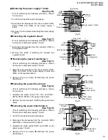
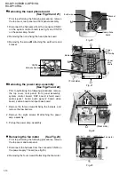
Prior to performing the following procedure, remove
the power amp. assembly.
Cut off the tie band fixing the harnesses.
Disconnect the harness from two connectors CN70
on the thermal compensation board (up side).
Remove the two screws A attaching the relay board.
Disconnect the harness from five connectors CN70
on the thermal compensation board (bottom side).
Pull up Lch pre amp., center pre amp., surround pre
amp. and Rch pre amp. with the relay board from the
power amp. board.
Remove each pre amp. board from the connector
CN721, CN821, CN781 and CN761 on the relay
board.
1.
2.
3.
4.
5.
6.
Removing the relay board & Rch pre amp.
& Lch pre amp. & center pre amp. &
surround pre amp. (See Fig.1 to 3)
<Power amp. assembly section>
Fig.1
Fig.2
Fig.3
Surround
pre amp.
Rch
pre amp.
Lch
pre amp.
CN70
(on Thermal
compensation
board)
CN70
(on Thermal
compensation
board)
Power amp. board
CN723
CN783
CN763
CN722
CN782
CN762
CN823
CN822
(Front side)
(Rear side)
Center
pre amp.
A
CN761
CN781
CN821
CN721
A
Power
amp.
assembly
(bottom side)
Harness
band
Tie band
Relay board
Power
amp.
assembly
(up side)
Summary of Contents for RX-DP10RSL
Page 61: ...RX DP10VBK RX DP10VSL RX DP10RSL 3 2 M E M O ...
Page 94: ...RX DP10VBK BX DP10VSL RX DP10RSL 3 35 M E M O ...
Page 97: ...RX DP10VBK RX DP10VSL RX DP10RSL 3 38 M E M O ...
Page 99: ...RX DP10VBK RX DP10VSL RX DP10RSL 3 40 M E M O ...
Page 130: ...RX DP10VBK BX DP10VSL RX DP10RSL 3 71 M E M O ...

