RX-DP10VBK/RX-DP10VSL
RX-DP10RSL
1-20
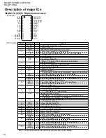
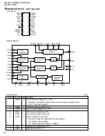
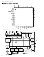
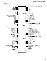
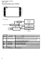
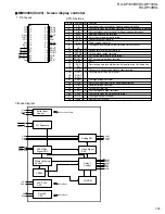
1. Pin layout
JCV8006 (IC635, IC640, IC645, IC650) : CC converter
VDD
FP1
FP2
WSN
WS
RAMT
VSS
CLK
VDD
DFR1
DFR2
DF1
DF2
DFSEL
SH
VSS
VDD
VCK
DIN
LRCK
CAD1
CAD0
RESET
VSS
MODE
MCK/IW2N
MDT/IW1N
MLEN/IOF
BT
D1W1
D1W2
VSS
VSS
TOUT6
TOUT7
TOUT8
TOUT9
TOUTA
TOUTD
VDD
TMD0
TMD1
CKSLN
PDN
CKDV
F192
TSTEN
VDD
VSS
T
OUT0
T
OUT1
T
OUT2
DOUT1
BCK
O1
WCK
O1
VDD
VSS
DOUT2
BCK
O2
WCK
O2
T
OUT3
T
OUT4
T
OUT5
VDD
49
50
51
52
53
54
55
56
57
58
59
60
61
62
63
64
1
2
3
4
5
6
7
8
9
10
11
12
13
14
15
16
32
31
30
29
28
27
26
25
24
23
22
21
20
19
18
17
48
47
46
45
44
43
42
41
40
39
38
37
36
35
34
33
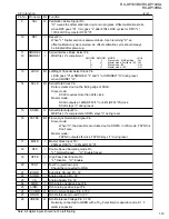
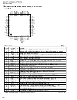
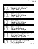
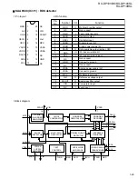
2. Pin function
(1/2)
Pin name
VDD
BCK
DIN
LRCK
CAD1
CAD0
RESET
VSS
MODE
MCK/IW2N
MDT/IW1N
MLEN/IOF
BTR
D1W1
D1W2
VSS
VDD
TSTEN
F192
CKDV
I/O
-
l1
l1
l1
lp2
lp2
l1
-
lp2
l1
l1
l1
lp2
lp2
lp2
-
-
lp2
lp2
lp2
Function
Power supply : All VDD pins must be connected externally
Bit clock input :Bit click if serial data into the DIN ; Must run continuously, "5V tolerant"
Serial audio data input, "5V tolerant"
Left/Right clock input ; sampling frequency (fs) for DIN ; Must run continuously, "5V tolerant"
Chip address 1 ; available on MODE=H
Chip address 0 ; available on MODE=H
System reset ; the internal state is reset to the default setting when L, "5V tolerant"
Ground ; All VSS pins must be connected externally
System control mode select input : (H=Software mode ; L=Hardware mode)
Control clock input ; MODE=H,
/Select input audio data word length input2 ; MODE=L, "5V tolerant"
Control data input ; MODE=H,
/Select input audio data word length input 1 ; MODE=L, "5V tolerant"
Control data latch input ; MODE=H,
/select input and output audio data format input ; MODE=L, "5V tolerant"
Select BIT-UP through mode input ; MODE=L
Select output 1 audio data word length and enable control 1 ; MODE=L
Select output 1 audio data word length and enable control 2 ; MODE=L
Ground ; All VSS pins must be connected externally
Power supply ; All VSS pins must be connected externally
Test control input ; in normal operation this pin should be terminated to ground
Select system clock for 192kHz input sampling frequency input : MODE=L,
(supported for FS-UP only)
Internal click divider select input ; MODE=L,(L=1, H=1/2)
Pin No.
1
2
3
4
5
6
7
8
9
10
11
12
13
14
15
16
17
18
19
20
l=CMOS, l1=Schmitt, lp2=Schmitt with pull-down resistor, O=CMOS
(H=VDD, L=VSS)
Summary of Contents for RX-DP10RSL
Page 61: ...RX DP10VBK RX DP10VSL RX DP10RSL 3 2 M E M O ...
Page 94: ...RX DP10VBK BX DP10VSL RX DP10RSL 3 35 M E M O ...
Page 97: ...RX DP10VBK RX DP10VSL RX DP10RSL 3 38 M E M O ...
Page 99: ...RX DP10VBK RX DP10VSL RX DP10RSL 3 40 M E M O ...
Page 130: ...RX DP10VBK BX DP10VSL RX DP10RSL 3 71 M E M O ...

