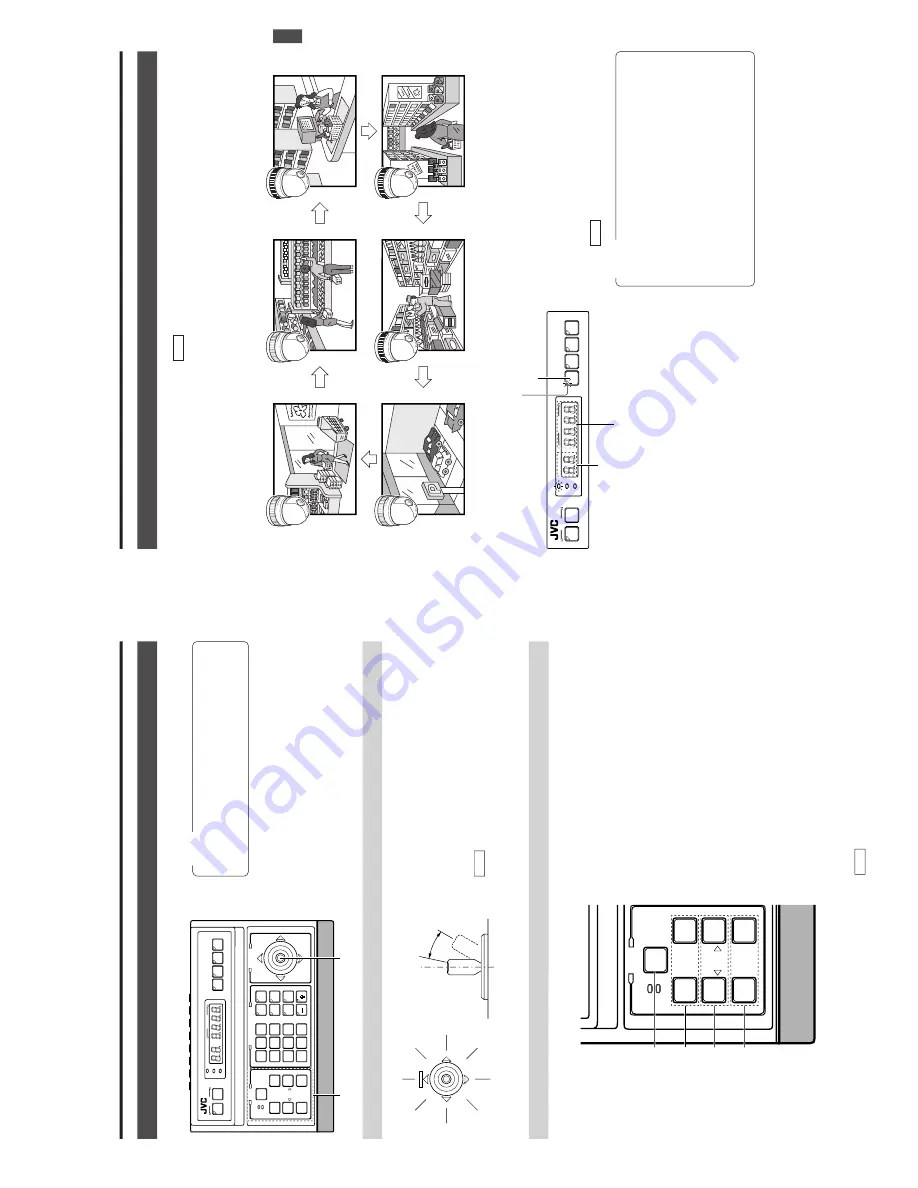
JVC RM-P2580 Instructions Manual Download Page 7

E-12

The man

ual operation allo

ws y

ou to P

AN or 

TIL

T the selected camera and to contr

ol its lens.

2.  BASIC OPERA

TIONS

MANU

AL OPERA

TION

NO

TES

Manual operation is not available in the 

AUT

O

SEQUENCE or 

AUT

O P

A

TROL

 modes.

Only the lever tilting operation is available in the 

AUT

O

P

AN mode.

Operating the P

AN/TIL

T Contr

ol Le

ver

The rotary turret of the camera rotates according to the di-

rection in which the P

AN/TIL

T

 lever is tilted.

The speed of rotation depends on the angle of tilt of the

control lever

The greater the tilt, the faster the speed.

The speed at each step value can be changed according

to the tilt angle.

IRIS

To

 adjust the video image brightness, press and hold one of

the IRIS control buttons until the desired brightness is ob-

tained.

CLOSE

: Closes the lens iris.

OPEN

: Opens the lens iris.

The iris operation continues as long as the button is being

pressed.

FOCUS

To

 adjust the focus, press and hold one of the FOCUS con-

trol buttons until the desired focus is obtained.

NEAR

: Brings a near object into focus.

FA

R

: Brings a far object into focus.

The focus operation continues for as long as the button is

being pressed.

ZOOM

To

 adjust the video image size, press and hold one of the

ZOOM control buttons until the desired size is obtained.

WIDE:

 Zooms out and widens the image.

TELE:


Zooms in and narrows the image.

The zoom operation continues for as long as the button is

being pressed.

Operating the Lens

Operation method

Speed

Low speed

High speed

Variable in

max. 8 steps

Up

Down

Upper left

Upper right

Lower left

Left

Right

Lower right

PAN/TILT

IRIS control buttons

SPEED buttons

 FOCUS control buttons

ZOOM control buttons

SETUP

MENU

SET

SPEED

IRIS

AF

FOCUS

ZOOM

OPEN

FAR

TELETELE

CLEAR

/HOME

7

4

1

8

0

5

2

9

6

3

ENTER

AUTO

PAN

OPTION

1

OPTION

2

CAMERA

POSI-

TION

AUTO

PATROL

CLOSE

NEAR

WIDE

AUTO

F-1

F-2

F-3

PAN/TILT

LENS

CAMERA/POSITION

CAMERA

POSITION

REMOTE CONTROL UNIT 

RM-P2580

ALARM

PO

WER

KEY LOCK

SETUP

MENU

SET

SPEED

IRIS

AF

FOCUSFOCUS

ZOOM

OPEN

FAR

TELE

CLEAR

/HOME

7

4

1

8

0

5

2

9

6

3

ENTER

AUTOAUTO

PANPAN

OPTION

1

OPTION

2

CAMERACAMERA

POSI-

TION

AUTOAUTO

PATROLPATROL

CLOSE

NEAR

WIDE

AUTO

F-1

F-2

F-3

PAN/TILT

LENS

CAMERA/POSITIONCAMERA/POSITION

CAMERA

POSITION

REMOTE CONTROL UNIT REMOTE CONTROL UNIT 

RM-P2580RM-P2580

ALARMALARM

POPO

WERWER

KEY LOCKKEY LOCK

Lens operation

PAN/TILT control lever

 REF

.

:

“P/T

 SPEED” on page 29 for how to change the lever

sensitivity

.

The movement speeds of zoom and focus are variable with

SPEED button.


REF

.   : “SPEED button” on the page 7.

E-13

AU

TO

 SEQUENCE OPERA

TION

Operation with the Basic System

 (  REF

.   : Page 32 for the switching interval setting.)

When the 

AUT

O button is pressed, the 

AUT

O indicator lights up and the MONIT

OR OUTPUT

 connectors output the camera

images, switching them in order of camera numbers at constant intervals.

(Example) 

When using cameras 1 to 6

2.  BASIC OPERA

TIONS

Camera 1

Camera 2

Camera 3

Camera 6

Camera 5

Camera 4

SETUPSETUP

MENUMENU

SETSET

AUTOAUTO

F-1

F-2

F-3F-3

CAMERACAMERA

POSITIONPOSITION

REMOTE CONTROL UNIT REMOTE CONTROL UNIT 

RM-P2580RM-P2580

ALARM

PO

WER

KEY LOCK

POSITION display

Lights up.

AUTO button

CAMERA display

2.

To

 stop the 

AUT

O SEQUENCE operation, press the 

AUT

O

button once again.

1.

Press the 

AUT

O button.

The LED indicator lights up and the 

AUT

O SEQUENCE

operation starts.

The CAMERA

 display shows the camera number of the

video being output from the MONIT

OR OUTPUT

 1 con-

nector

.

The POSITION display shows the camera operation de-

tails. (  REF

.   : Page 10)

NO

TES

During the 

AUT

O SEQUENCE operation, the camera

selection, manual selection, 

AUT

O P

AN operation and

AUT

O P

A

TROL

 operation are not available.

When the auto mode 

AUT

O SEQUENCE operation is

switched from ON to OFF

, the MONIT

OR OUTPUT

 con-

nectors output the video at the moment of the ON-OFF

switching.

In the case of Applied System (B Mode), the video from

the MONIT

OR OUTPUT

 is displayed in either auto se-

quence or in multi-split screen depending on the setting

of the connected frame switcher

.

Summary of Contents for RM-P2580

Page 1: ... F 3 F 3 PAN TILT LENS CAMERA POSITION ALARM ALARM CAMERA CAMERA POSITION POSITION REMOTE CONTROL UNIT RM P2000 KEY LOCK KEY LOCK E model LWT0111 U model LWT0110 R Printed in Japan E model LWT0111 U model LWT0110 SETUP MENU MENU SET SPEED IRIS AF FOCUS ZOOM OPEN OPEN FAR FAR TELE TELE CLEAR CLEAR HOME HOME 7 4 1 8 0 5 2 9 6 3 ENTER ENTER AUTO AUTO PAN PAN OPTION OPTION 1 OPTION OPTION 2 CAMERA CAM...

Page 2: ...to persons The exclamation point within an equilateral tri angle is intended to alert the user to the pres ence of important operating and maintenance servicing instructions in the literature accom panying the appliance WARNING TO REDUCE THE RISK OF FIRE OR ELECTRIC SHOCK DO NOT EXPOSE THIS APPLIANCE TO RAIN OR MOISTURE Changes or modifications not approved by JVC could void the user s authority t...

Page 3: ... CAMERA POSITION ALARM ALARM PO POWER WER CAMERA CAMERA POSITION POSITION REMOTE CONTROL UNIT RM P2580 KEY LOCK KEY LOCK INTRODUCTION BASIC OPERATIONS APPLIED OPERATIONS OTHER CONNECTIONS MENU SCREEN SETUPS Precautions for the PRESET SEQUENCE and AUTO PAN Operations The life span of the PRESET SEQUENCE and AUTO PAN functions is dependent on which camera model is used in combination with this unit ...

Page 4: ...gent REF APPLIED SYSTEM B MODE on page 22 F1 Single screen select switch Press this button to output a single screen video from the frame switcher The camera number can be selected using the numeric keypad etc F2 Split screen select switch Press this button to output a split screen video from the frame switcher F3 LIVE PLAY switch Press this button to switch between the playback video of a time la...

Page 5: ...ideo signals from the cam eras When this unit is operated in the B mode apply the output signal from a frame switcher to the VIDEO INPUT 1 con nector REF BASIC SYSTEM on page 19 APPLIED SYSTEM on page 21 VIDEO OUTPUT Video signal output connectors Each of these connectors outputs the video signal corre sponding to the VIDEO INPUT connector above it Connect these connectors to a video device such a...

Page 6: ...at the indicator lights up 2 Input the position number using the numeric keys 0 to 9 The input figure is shown in the POSITION display to gether with a period after it Example When 48 is input To clear the input figure press the CLEAR button 4 To view the video of the next recorded position number press the button To view the video of the previous re corded position number press the button 3 Press...

Page 7: ...OL UNIT RM P2580 ALARM POWER KEY LOCK SETUP MENU SET SPEED IRIS AF FOCUS FOCUS ZOOM OPEN FAR TELE CLEAR HOME 7 4 1 8 0 5 2 9 6 3 ENTER AUTO AUTO PAN PAN OPTION 1 OPTION 2 CAMERA CAMERA POSI TION AUTO AUTO PATROL PATROL CLOSE NEAR WIDE AUTO F 1 F 2 F 3 PAN TILT LENS CAMERA POSITION CAMERA POSITION CAMERA POSITION REMOTE CONTROL UNIT REMOTE CONTROL UNIT RM P2580 RM P2580 ALARM ALARM PO POWER WER KEY...

Page 8: ... UNIT RM P2580 ALARM POWER WER KEY LOCK AUTO PAN button PAN TILT control lever POSITION display SET button E 15 2 BASIC OPERATIONS AUTO PATROL OPERATION The AUTO PATROL operation consists of high speed camera movement between multiple pre set positions in a sequence and at time intervals set by the user This function can be set on individual cameras 1 Press the AUTO PATROL button The LED indicator...

Page 9: ...e in the alarm priority mode the buzzer does not sound and the camera in question is not automatically selected 3 APPLIED OPERATIONS ALARM OPERATION Alarm input signals can be applied to the DATA I O terminals on the rear panel The unit functions in either the ALARM PRIORITY mode or the MANUAL PRIORITY mode when an alarm signal is input REF CONTROL UNIT SCREEN on page 28 and PRIORITY item of ALARM...

Page 10: ...s the MAKE position until the alarm conditions for all the cameras have been cleared NOTE When the ALARM TIME is set to SERIES the alarm condition continues until the preset position of the camera to which the alarm signal was input is selected The alarm operation stops automatically when specified time has elapsed When the time period specified in the ALARM TIME item in the ALARM screen has elaps...

Page 11: ...ed 4 CONNECTIONS The master monitor displays the video signal from the selected camera Use the CAMERA SW input to switch the video signal and record it on the VCR The preset operation manual operation AUTO PAN operation and AUTO PATROL operation are available for each camera When fixed cameras are used only the video signal can be switched The alarm operation is available using the DATA I O termin...

Page 12: ...16 alarm inputs is available by using the DATA I O terminals Alarms with up to 100 positions per camera can be handled via the SERIAL 1 connector NOTES MANUAL operation of cameras and the menu operation are available even in the auto mode As the frame switcher control signal is not output the information in the CAMERA display does not change E 23 The electrical standards applied to the SERIAL 1 an...

Page 13: ... DATA I O COM 1 2 3 4 5 6 7 8 COM 9 1 10 2 11 3 12 4 13 5 14 6 15 7 16 8 COM COM COM CAMERA CAMERA SW UNIT UNIT ALARM AUTO HOLD Install a ferrite core on cables connected to the DATA I O ter minals and to the TO CAMERA terminals as shown in the dia gram on the left Keep the ferrite core as close as possible to the remote control unit Installing the Ferrite Core ACCESSORY E 25 5 MENU SCREEN SETUPS ...

Page 14: ... ENTER button In this case the camera screen shifts to the pre regis tered POSITION 5 Set the image angle Set it using the PAN TILT control lever and the IRIS ZOOM and FOCUS control buttons 6 Press the SET button for about 1 second A short beep indicates that the position has been memo rised Invalid operation is displayed when using the camera which the position can not be preset such as fixed cam...

Page 15: ... CLOSE CLOSE NEAR WIDE AUTO F 1 F 2 F 3 PAN TILT LENS LENS CAMERA POSITION CAMERA POSITION CAMERA POSITION POSITION REMOTE CONTROL UNIT REMOTE CONTROL UNIT RM P2580 RM P2580 ALARM ALARM POWER KEY LOCK KEY LOCK SET button MENU button CONTROL UNIT OPTION DATA I O ALARM AUTO SEQUENCE SETUP POSITION SETUP CAMERA CONTROL UNIT 2 3 2 Displayed in A mode only E 29 OPTION SCREEN 5 MENU SCREEN SETUPS Item M...

Page 16: ... set value be sure to turn the power from OFF ON in order to register the reset values Set the assignment of the DATA I O to be used as the input mode REF Page 31 DATA I O CAM SWITCH LOW I O 16ALM IN INPUT ASSIGNMENT INPUT ASSIGNMENT TERMINAL 1 CAMERA IGNORE POSITION HOME ALARM TEXT NONE POLARITY MAKE NOTE When the I O item above is selected to any of the following items the INPUT ASSIGNMENT scree...

Page 17: ...tion manuals of the cameras in use Is the unit in the KEY LOCK status Are the cameras connected properly to the TO CAMERA connectors Are the DIP switches of the cameras set properly REF Instruction manuals of the cameras in use Is the unit in the KEY LOCK status Are the camera IDs set to match correctly the VIDEO INPUT connector numbers Is MAX CAMERA set to match the number of connected cameras Is...

Page 18: ...Dimensions Unit mm Design and specifications are subject to change without notice 1 TO CAMERA DATA I O RX RX TX TX COM 1 2 3 4 5 6 7 8 COM 9 1 9 1 10 2 10 2 11 3 11 3 12 4 12 4 13 5 13 5 14 6 14 6 15 7 15 7 16 8 16 8 COM COM COM CAMERA CAMERA SW SW UNIT UNIT ALARM AUTO AUTO 4 3 1 2 8 7 5 6 2 3 4 5 6 7 8 1 MONITOR OUTPUT MONITOR SERIAL 2 SERIAL 2 SERIAL 1 VIDEO INPUT VIDEO INPUT VIDEO OUTPUT VIDEO ...

Reviews: