JVC RM-P2580 Instructions Manual Download Page 4

E-6

!

[POSITION] b

utton

Press when selecting one of the position numbers preset

for the camera.

To

 select a position, use the following buttons:

POSITION button 

!


 Numeric key buttons 

*


 EN-

TER button 

&

.

REF

.:

 “POSITION SELECTION” on page 1

1.

@

[OPTION 1, 2]

These buttons are not used for the present. Do not touch

them.

#

[P

AN/TIL

T] contr

ol le

ver

Operate the lever to pan (swing horizontally) or tilt (swing

vertically) the rotary turret of a camera.

8

(Up)

:

T

ilt the lever in this direction to tilt the rotary

turret upward.

9

(Down)

:

T

ilt the lever in this direction to tilt the rotary

turret downward.

:

(Right)

:

T

ilt the lever in this direction to pan the rotary

turret toward the right.

;

(Left)

:

T

ilt the lever in this direction to pan the rotary

turret toward the left.

REF

.:

 “MANUAL

 OPERA

TION” on page 12.

While a menu screen is displayed, this lever is used to

select or to set an item.

REF

.:

 “MENU OPERA

TION METHOD” on page 26.
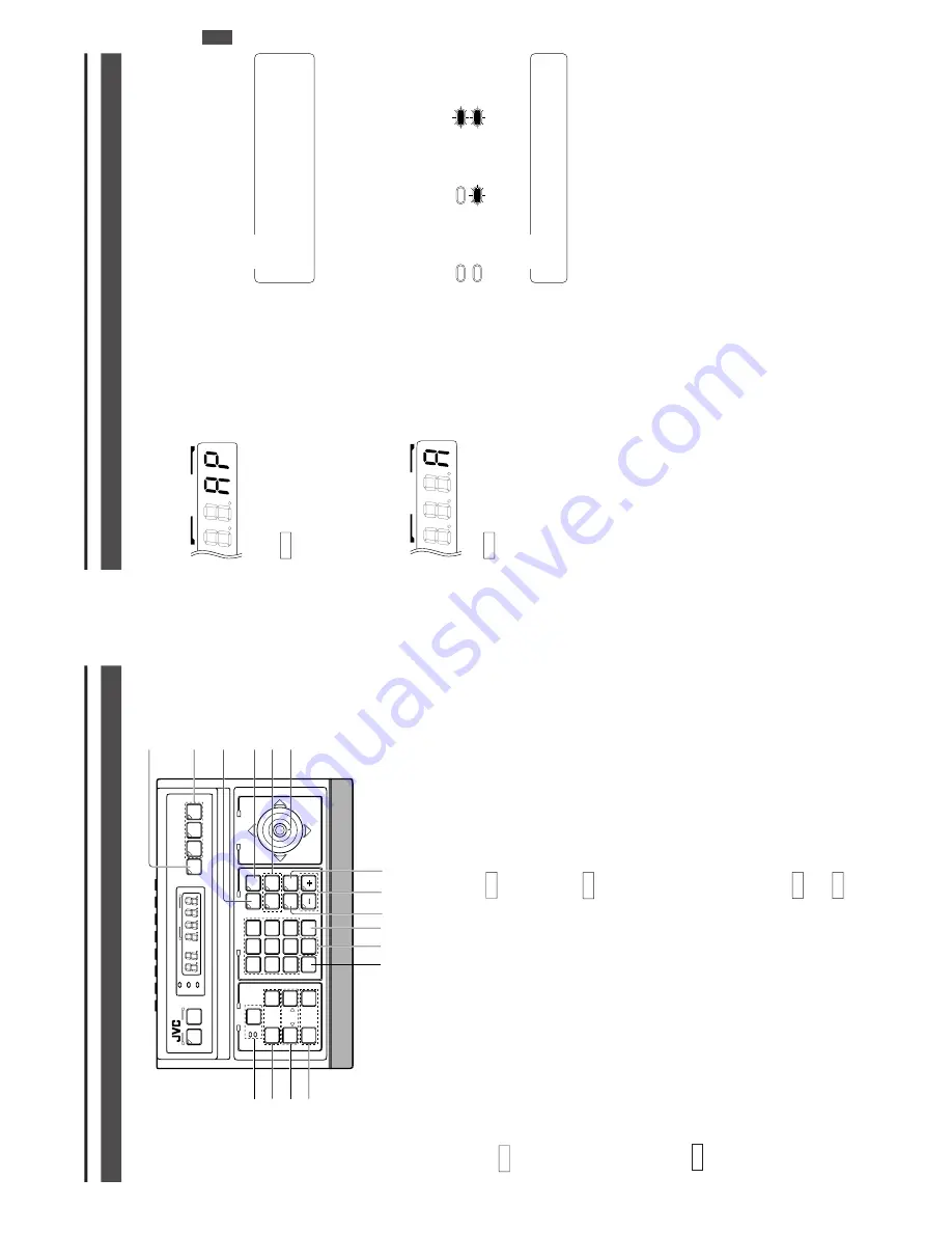
1. INTRODUCTION

CONTR

OLS,

 CONNECT

ORS AND INDICA

T

ORS (Continued)

SETUPSETUP

MENUMENU

SETSET

SPEEDSPEED

IRIS

AF

FOCUS

ZOOM

OPENOPEN

FARFAR

TELETELE

CLEARCLEAR

/HOME/HOME

7

4

1

8

0

5

2

9

6

3

ENTERENTER

AUTOAUTO

PAN

OPTIONOPTION

1

OPTIONOPTION

2

CAMERACAMERA

POSI-POSI-

TIONTION

AUTOAUTO

PATROLPATROL

CLOSECLOSE

NEARNEAR

WIDEWIDE

AUTOAUTO

F-1F-1

F-2F-2

F-3F-3

PAN/TILT

LENS

CAMERA/POSITION

CAMERACAMERA

POSITIONPOSITION

REMOTE CONTROL UNIT REMOTE CONTROL UNIT 

RM-P2580

ALARM

PO

WER

KEY LOCK

*&
(

¤

)

$

^

%

9

@

#

0

8

!

0

[CAMERA] b

utton

Press when selecting a camera.

To

 select a camera, use the following buttons:

CAMERA button 

0


 Numeric key buttons 

*


ENTER button 

&

.

REF

.

: “CAMERA SELECTION” on page 10.

8

[A

UT

O] b

utton

When this button is pressed, the unit enters the 

AUT

O SE-

QUENCE mode, in which the indicator lights up and the

MONIT

OR OUTPUT

 1 connector 

 on the rear panel out-

put the camera video signals according to automatic switch-

ing.

REF

.

: “AUT

O SEQUENCE OPERA

TION” on page 13.

9

[F1,

 F2,

 F3] Function b

uttons

E model

These buttons are not used for the present. Do not touch

them.

U model

These buttons are valid only when SW

-D7000/SW

-D8000

frame switchers are being used.

When this unit is operated in the B mode, these buttons

can control certain functions of the specific frame switcher

model connected to this unit. 

The RS-232C control is in-

volved in this control operation.

For details, please consult your dealer or JVC-authorized

service agent.

REF

.:

 “APPLIED SYSTEM (B MODE)” on page 22.

F1

:

Single-screen select s

witc

h

Press this button to output a single-screen video from

the frame switcher

.

The camera number can be selected using the numeric

keypad

, etc.

F2

:

Split-screen select s

witc

h

Press this button to output a split-screen video from

the frame switcher

.

F3:

LIVE/PLA

Y s

witc

h

Press this button to switch between the playback video

of a time-lapse VCR and the camera video.

E-7

The 

AUT

O P

A

TROL

 function can be set on a per-camera

basis.

REF

.:

 “AUT

O P

A

TROL

 OPERA

TION” on page 15.

%

[–,

 +] Negative and positive b

uttons

Press button to decrease or increase the camera or posi-

tion number

.

^

[A

UT

O P

AN] b

utton

Press this button to rotate or swing a camera between pre-

set positions at a preset time interval.

1. INTRODUCTION

CONTR

OLS,

 CONNECT

ORS AND INDICA

T

ORS (Continued)

$

[A

UT

O P

A

TR

OL] b

utton

Press this button to switch the camera positions automati-

cally in a preset order and at preset time intervals.

The POSITION display be-

comes as shown on the left

during AUT

P

A

TROL.

REF

.:

 “AUT

O P

AN OPERA

TION” on page 14.

&

[ENTER] b

utton

Press to enter a figure input using the numeric key buttons

*

.

*

[1 to 0/HOME] Numeric ke

y b

uttons

Use these buttons to choose a camera or position number

.

(

[CLEAR] b

utton

Press to clear an input figure before it is entered by press-

ing the ENTER button.

)

[ZOOM 

WIDE,

 TELE] ZOOM contr

ol b

uttons

Press and hold to control the ZOOM operation of the cam-

era lens.

WIDE:

 Zooms out and widens the image.

TELE:


Zooms in and narrows the image.

[FOCUS NEAR,

 F

AR] FOCUS  contr

ol b

uttons

   ●

Press and hold to control the FOCUS operation of the cam-

era lens.

NEAR

:


Brings a near object in focus.

FA

R

: Brings a distant object in focus.

   ●

AF (AUT

O FOCUS)

When the NEAR and F

AR buttons are simultaneously

pressed and held for about 1 second, a short beep is gen-

erated and the object is automatically brought into focus.

The POSITION display be-

comes as shown on the left

during AUT

P

AN.

¤

[IRIS CLOSE,

 OPEN]  Iris contr

ol b

utton.

Press and hold to control the lens iris.

CLOSE

: Closes the lens iris.

OPEN

: Opens the lens iris.

[SPEED] Speed b

utton and indicator

s

Press to set the speed of the ZOOM and FOCUS control

operations.

Each press of the button changes the operation speed.

POSITION

POSITION

: Low speed

: Medium speed 

: High speed

NO

TE

When the power is turned on, the operation speed is

medium.

NO

TE

If the camera being selected does not incorporate the

AUT

O FOCUS function, this function is not available

even when the short beep is generated. Be sure to use

this function while observing the monitor screen.

Summary of Contents for RM-P2580

Page 1: ... F 3 F 3 PAN TILT LENS CAMERA POSITION ALARM ALARM CAMERA CAMERA POSITION POSITION REMOTE CONTROL UNIT RM P2000 KEY LOCK KEY LOCK E model LWT0111 U model LWT0110 R Printed in Japan E model LWT0111 U model LWT0110 SETUP MENU MENU SET SPEED IRIS AF FOCUS ZOOM OPEN OPEN FAR FAR TELE TELE CLEAR CLEAR HOME HOME 7 4 1 8 0 5 2 9 6 3 ENTER ENTER AUTO AUTO PAN PAN OPTION OPTION 1 OPTION OPTION 2 CAMERA CAM...

Page 2: ...to persons The exclamation point within an equilateral tri angle is intended to alert the user to the pres ence of important operating and maintenance servicing instructions in the literature accom panying the appliance WARNING TO REDUCE THE RISK OF FIRE OR ELECTRIC SHOCK DO NOT EXPOSE THIS APPLIANCE TO RAIN OR MOISTURE Changes or modifications not approved by JVC could void the user s authority t...

Page 3: ... CAMERA POSITION ALARM ALARM PO POWER WER CAMERA CAMERA POSITION POSITION REMOTE CONTROL UNIT RM P2580 KEY LOCK KEY LOCK INTRODUCTION BASIC OPERATIONS APPLIED OPERATIONS OTHER CONNECTIONS MENU SCREEN SETUPS Precautions for the PRESET SEQUENCE and AUTO PAN Operations The life span of the PRESET SEQUENCE and AUTO PAN functions is dependent on which camera model is used in combination with this unit ...

Page 4: ...gent REF APPLIED SYSTEM B MODE on page 22 F1 Single screen select switch Press this button to output a single screen video from the frame switcher The camera number can be selected using the numeric keypad etc F2 Split screen select switch Press this button to output a split screen video from the frame switcher F3 LIVE PLAY switch Press this button to switch between the playback video of a time la...

Page 5: ...ideo signals from the cam eras When this unit is operated in the B mode apply the output signal from a frame switcher to the VIDEO INPUT 1 con nector REF BASIC SYSTEM on page 19 APPLIED SYSTEM on page 21 VIDEO OUTPUT Video signal output connectors Each of these connectors outputs the video signal corre sponding to the VIDEO INPUT connector above it Connect these connectors to a video device such a...

Page 6: ...at the indicator lights up 2 Input the position number using the numeric keys 0 to 9 The input figure is shown in the POSITION display to gether with a period after it Example When 48 is input To clear the input figure press the CLEAR button 4 To view the video of the next recorded position number press the button To view the video of the previous re corded position number press the button 3 Press...

Page 7: ...OL UNIT RM P2580 ALARM POWER KEY LOCK SETUP MENU SET SPEED IRIS AF FOCUS FOCUS ZOOM OPEN FAR TELE CLEAR HOME 7 4 1 8 0 5 2 9 6 3 ENTER AUTO AUTO PAN PAN OPTION 1 OPTION 2 CAMERA CAMERA POSI TION AUTO AUTO PATROL PATROL CLOSE NEAR WIDE AUTO F 1 F 2 F 3 PAN TILT LENS CAMERA POSITION CAMERA POSITION CAMERA POSITION REMOTE CONTROL UNIT REMOTE CONTROL UNIT RM P2580 RM P2580 ALARM ALARM PO POWER WER KEY...

Page 8: ... UNIT RM P2580 ALARM POWER WER KEY LOCK AUTO PAN button PAN TILT control lever POSITION display SET button E 15 2 BASIC OPERATIONS AUTO PATROL OPERATION The AUTO PATROL operation consists of high speed camera movement between multiple pre set positions in a sequence and at time intervals set by the user This function can be set on individual cameras 1 Press the AUTO PATROL button The LED indicator...

Page 9: ...e in the alarm priority mode the buzzer does not sound and the camera in question is not automatically selected 3 APPLIED OPERATIONS ALARM OPERATION Alarm input signals can be applied to the DATA I O terminals on the rear panel The unit functions in either the ALARM PRIORITY mode or the MANUAL PRIORITY mode when an alarm signal is input REF CONTROL UNIT SCREEN on page 28 and PRIORITY item of ALARM...

Page 10: ...s the MAKE position until the alarm conditions for all the cameras have been cleared NOTE When the ALARM TIME is set to SERIES the alarm condition continues until the preset position of the camera to which the alarm signal was input is selected The alarm operation stops automatically when specified time has elapsed When the time period specified in the ALARM TIME item in the ALARM screen has elaps...

Page 11: ...ed 4 CONNECTIONS The master monitor displays the video signal from the selected camera Use the CAMERA SW input to switch the video signal and record it on the VCR The preset operation manual operation AUTO PAN operation and AUTO PATROL operation are available for each camera When fixed cameras are used only the video signal can be switched The alarm operation is available using the DATA I O termin...

Page 12: ...16 alarm inputs is available by using the DATA I O terminals Alarms with up to 100 positions per camera can be handled via the SERIAL 1 connector NOTES MANUAL operation of cameras and the menu operation are available even in the auto mode As the frame switcher control signal is not output the information in the CAMERA display does not change E 23 The electrical standards applied to the SERIAL 1 an...

Page 13: ... DATA I O COM 1 2 3 4 5 6 7 8 COM 9 1 10 2 11 3 12 4 13 5 14 6 15 7 16 8 COM COM COM CAMERA CAMERA SW UNIT UNIT ALARM AUTO HOLD Install a ferrite core on cables connected to the DATA I O ter minals and to the TO CAMERA terminals as shown in the dia gram on the left Keep the ferrite core as close as possible to the remote control unit Installing the Ferrite Core ACCESSORY E 25 5 MENU SCREEN SETUPS ...

Page 14: ... ENTER button In this case the camera screen shifts to the pre regis tered POSITION 5 Set the image angle Set it using the PAN TILT control lever and the IRIS ZOOM and FOCUS control buttons 6 Press the SET button for about 1 second A short beep indicates that the position has been memo rised Invalid operation is displayed when using the camera which the position can not be preset such as fixed cam...

Page 15: ... CLOSE CLOSE NEAR WIDE AUTO F 1 F 2 F 3 PAN TILT LENS LENS CAMERA POSITION CAMERA POSITION CAMERA POSITION POSITION REMOTE CONTROL UNIT REMOTE CONTROL UNIT RM P2580 RM P2580 ALARM ALARM POWER KEY LOCK KEY LOCK SET button MENU button CONTROL UNIT OPTION DATA I O ALARM AUTO SEQUENCE SETUP POSITION SETUP CAMERA CONTROL UNIT 2 3 2 Displayed in A mode only E 29 OPTION SCREEN 5 MENU SCREEN SETUPS Item M...

Page 16: ... set value be sure to turn the power from OFF ON in order to register the reset values Set the assignment of the DATA I O to be used as the input mode REF Page 31 DATA I O CAM SWITCH LOW I O 16ALM IN INPUT ASSIGNMENT INPUT ASSIGNMENT TERMINAL 1 CAMERA IGNORE POSITION HOME ALARM TEXT NONE POLARITY MAKE NOTE When the I O item above is selected to any of the following items the INPUT ASSIGNMENT scree...

Page 17: ...tion manuals of the cameras in use Is the unit in the KEY LOCK status Are the cameras connected properly to the TO CAMERA connectors Are the DIP switches of the cameras set properly REF Instruction manuals of the cameras in use Is the unit in the KEY LOCK status Are the camera IDs set to match correctly the VIDEO INPUT connector numbers Is MAX CAMERA set to match the number of connected cameras Is...

Page 18: ...Dimensions Unit mm Design and specifications are subject to change without notice 1 TO CAMERA DATA I O RX RX TX TX COM 1 2 3 4 5 6 7 8 COM 9 1 9 1 10 2 10 2 11 3 11 3 12 4 12 4 13 5 13 5 14 6 14 6 15 7 15 7 16 8 16 8 COM COM COM CAMERA CAMERA SW SW UNIT UNIT ALARM AUTO AUTO 4 3 1 2 8 7 5 6 2 3 4 5 6 7 8 1 MONITOR OUTPUT MONITOR SERIAL 2 SERIAL 2 SERIAL 1 VIDEO INPUT VIDEO INPUT VIDEO OUTPUT VIDEO ...

Reviews: