


E-10
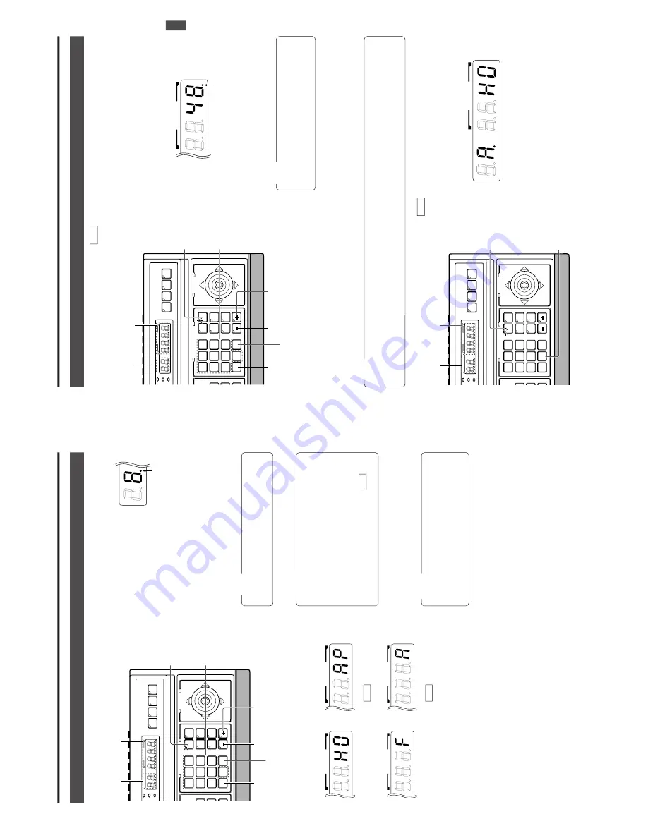
Selecting a Desired Camera
2. BASIC OPERA
TIONS
CAMERA SELECTION
1.
Press the CAMERA
button so that the indicator lights up.
2.
Input the camera number using the numeric keys (0 to 9).
The input figure is shown in the
CAMERA
display together with
a period after it. (Example: When
“8” is input)
To
clear the input figure, press
the CLEAR button.
3.
Press the ENTER button to enter the input camera number
.
The video of the selected camera will be output from the
MONIT
OR OUTPUT
connectors on the rear panel.
At this time, the period in the CAMERA
display disappears
and the POSITION display shows the camera operation
details (position, fixed camera,
AUT
O P
A
TROL,
AUT
O
P
AN, etc.).
NO
TES
●
When no camera is connected to a camera number
,
the camera number is skipped.
●
Be sure to set each camera ID to the same number
as the corresponding VIDEO INPUT
connector
. Er-
roneous settings may cause operational dif
ficulties.
4.
To
view the video of the next camera number
, press the +
button.
T
o
view the video of the previous camera number
,
press the – button.
SETUP
MENU
SET
SPEED
IRIS
AF
FOCUS
ZOOM
OPEN
FAR
TELE
CLEAR
/HOME/HOME
7
4
1
8
0
5
2
9
6
3
ENTER
AUTO
PAN
OPTIONOPTION
1
OPTION
2
CAMERA
POSI-
TION
AUTO
PATROL
CLOSE
NEAR
WIDE
AUTO
F-1
F-2
F-3
PAN/TILT
LENS
CAMERA/POSITIONCAMERA/POSITION
CAMERACAMERA
POSITIONPOSITION
REMOTE CONTROL UNIT
RM-P2580
ALARM
PO
WER
KEY LOCK
CAMERA
button
Numeric key
buttons
+ button
CLEAR button
ENTER button
- button
CAMERA display
POSITION display
CAMERA
Period
Camera operation details
NO
TE
●
“Camera video” is one of the video signals input to
the VIDEO INPUT
connector of this unit or to the
switcher
, etc.
POSITION
POSITION
POSITION
POSITION
Fixed camera display
Position display
(Example with the
home position)
AUTO PATROL
( REF. : Page 15)
AUTO PAN
( REF. : Page 14)
NO
TES
●
“Camera video” is one of the video signals input to
the VIDEO INPUT
connector of this unit or to the frame
switcher
.
●
In the case of the B mode in which the output video is
controlled by the frame switcher
, in order to allow cam-
era selection from this unit, connect the SERIAL-2
connector on the rear panel of the unit with the RS-
232C connector of the frame switcher
. ( REF
. : “AP-
PLIED SYSTEM (B MODE)” on page 22.)
E model
U model
E-11
Selecting a Desired Preset P
osition
( REF
. : Page 27 for the position presetting.)
2. BASIC OPERA
TIONS
POSITION SELECTION
1.
Press the POSITION button so that the indicator lights up.
2.
Input the position number using the numeric keys (0 to 9).
The input figure is shown in the POSITION display to-
gether with a period after it.
(Example: When “48” is input)
To
clear the input figure, press the CLEAR button.
4.
To
view the video of the next recorded position number
,
press the + button.
To
view the video of the previous re-
corded position number
, press the – button.
3.
Press the ENTER button to enter the input position number
.
The video of the selected position will be output from the
MONIT
OR OUTPUT
connectors on the rear panel.
At this time, the period in the POSITION display disap-
pears.
NO
TE
When a position number that has not been preset is
selected, the POSITION display shows the selected
position number but the video is not switched to that
position, etc.
SETUP
MENU
SET
SPEED
IRIS
AF
FOCUS
ZOOM
OPEN
FAR
TELE
CLEAR
/HOME/HOME
7
4
1
8
0
5
2
9
6
3
ENTER
AUTO
PAN
OPTION
1
OPTION
2
CAMERA
POSI-
TION
AUTO
PATROLPATROL
CLOSE
NEAR
WIDE
AUTOAUTO
F-1F-1
F-2F-2
F-3
PAN/TILT
LENS
CAMERA/POSITION
CAMERACAMERA
POSITIONPOSITION
REMOTE CONTROL UNIT REMOTE CONTROL UNIT
RM-P2580
ALARM
PO
WER
KEY LOCK
POSITION
button
Numeric key
buttons
+ button
CLEAR button
ENTER button
- button
CAMERA display
POSITION display
POSITION
Period
Setting All Cameras to the Home P
ositions
( REF
. : Page 27 for the home position presetting.)
1.
Press the CAMERA
button so that the indicator lights up.
2.
Press the HOME button.
The CAMERA
display shows “
A
”
and POSITION display shows “
H0
”.
3.
Press the ENTER button to move all the cameras into
their home positions.
When the cameras have moved to the home positions,
the CAMERA
display shows the camera number that was
selected before the HOME button was pressed.
SETUP
MENU
SET
SPEED
IRIS
AF
FOCUS
ZOOM
OPEN
FAR
TELE
CLEARCLEAR
/HOME/HOME
7
4
1
8
0
5
2
9
6
3
ENTERENTER
AUTOAUTO
PANPAN
OPTIONOPTION
1
OPTIONOPTION
2
CAMERACAMERA
POSI-POSI-
TIONTION
AUTOAUTO
PATROLPATROL
CLOSE
NEAR
WIDE
AUTOAUTO
F-1F-1
F-2F-2
F-3F-3
PAN/TILT
LENS
CAMERA/POSITION
CAMERACAMERA
POSITIONPOSITION
REMOTE CONTROL UNIT REMOTE CONTROL UNIT
RM-P2580
ALARM
PO
WER
KEY LOCK
CAMERA display
POSITION display
CAMERA
button
HOME
button
CAMERA
POSITION
U model onl
y
NO
TE
When
TK-C675B cameras are used, make sure that the lower 4 digits inscribed on the serial number on their rear panels are as
shown below
. Otherwise the cameras cannot be moved to the desired positions.
TK-C675BU: #0060 or after
When the serial number of a camera is other than the above, please consult your nearest JVC-authorized service agent.


