


RC-BX30
1-9
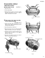
Fig.16
Fig.17
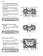
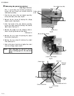
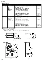
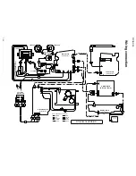
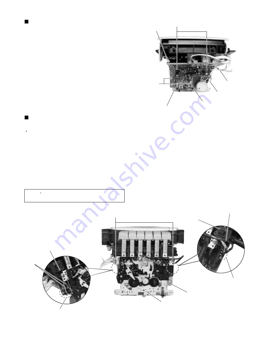
Removing the cassette board
(See Fig. 16.)
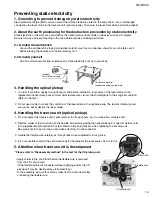
1.
2.
3.
4.
From the back side of the cassette deck
mechanism assembly, remove the tie band
bundling the wires.
Remove the solders from the soldered section
m
connecting the wires of the capstan motor and leaf
switch.
Remove the four screws
M
retaining the cassette
board.
From the reverse side of the cassette board,
remove the solders from the soldered section
n
connecting the wires of the REC/PB head.
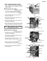
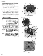
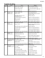
Removing the cassette deck
mechanism assembly
(See Fig. 17.)
1.
2.
3.
Remove the solders from the soldered section
p
connecting the wires of the leaf switch.
Remove the solders from the soldered section
q
connecting the wires of the REC/PB head.
Remove the two screws
N
retaining the cassette
deck mechanism assembly.
Prior to performing the following procedures,
remove the display board.
[Note]
When attaching the screws N, apply a
locking agent to the screws N.
M
N
M
Cassette board
Tie band
Soldered section
m
Cassette deck
mechanism assembly
Cassette deck
mechanism assembly
Cassette board
Soldered section
q
Soldered section
p
Cassette board
Wires (REC/PB head)
Soldered section
n
Cassette board
Wires
(Leaf switch)
Summary of Contents for RC-BX30
Page 23: ...RC BX30 1 23 M E M O ...


